.png)

Introduction
The most recent Intergovernmental Panel on Climate Change (IPCC) Assessment Report highlighted the key role of carbon capture in climate change mitigation1. Electrochemical carbon capture (ECC) processes are rapidly emerging as an alternative to conventional thermally driven amine scrubbing for carbon capture, effectively addressing several challenges of conventional processes, such as high energy requirements for separation and significant absorbent degradation2,3,4. ECC systems also offer inherent advantages of electrochemical technologies, including high efficiency, modularity, ease of retrofitting, and scalability2,5. ECC processes have been successfully implemented for carbon dioxide (CO2) separation from point sources6,7, direct air capture (DAC)8,9, and, most recently, from seawater10,11.
Depending on how redox reactions are involved, ECCs can be categorized into four broad groups2: (1) electrochemical generation of nucleophiles12,13,14,15, (2) electrochemical modulation of proton concentration (also known as pH-swing processes)16,17,18,19,20, (3) electrochemical capacitive adsorption21,22,23, and (4) electrochemically mediated amine regeneration24,25,26. Additionally, some earlier-stage electrochemical systems are emerging, such as electrochemical mineralization by direct amine–CO2 reduction27,28. Among these systems, electrochemically mediated amine regeneration (EMAR) has advanced to higher technology readiness levels; it has progressed from small-scale laboratory settings24 to pilot-scale implementations, demonstrating continuous CO2 capture for extended periods nearing one week25.
The EMAR process operates similarly to conventional amine-based thermal approaches, but instead of using a high-temperature scrubbing stage (typically at 120 °C), it employs a two-compartment electrochemical cell that operates at low to moderate temperatures (<50 °C). In this process, CO2 is separated through chemical reactions in the absorption column. The CO2-rich solution is then directed to the anode compartment of the electrochemical desorption unit, where the oxidation of the metal electrode and its subsequent complexation reaction with the absorbent releases the captured CO2. This stream is then sent to a flash tank for CO2 removal and subsequently to the cathode for absorbent regeneration, where the metal center of the metal-absorbent complex is deposited back on the electrode. The CO2-lean stream is then returned to the absorption column for reuse (Fig. 1A).
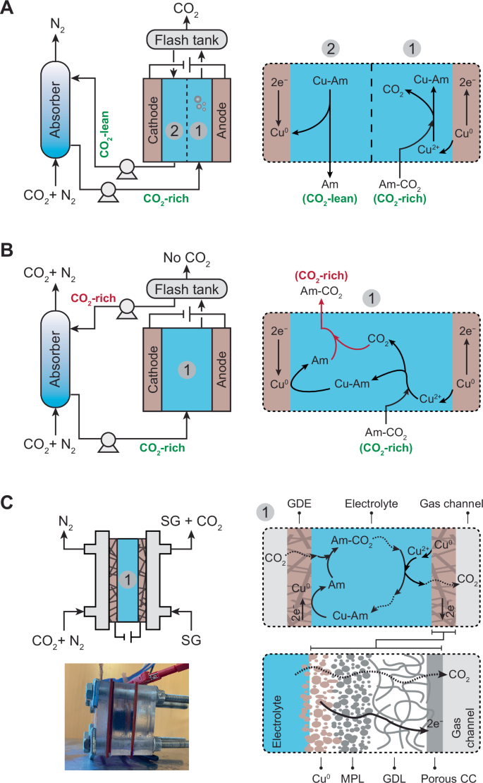
A Process scheme of the conventional EMAR with a two-compartment electrochemical cell separated by an anion exchange membrane (AEM), illustrated as a dashed line. The system also includes an absorption column, pumps, and a flash tank. B Conventional EMAR without the AEM. In this configuration, the desorbed CO2 at the anode is reabsorbed by the regenerated absorbent at the cathode, leading to low removal efficiency. C Developed membraneless EMAR with gas diffusion electrodes (GDEs). On the cathode side, CO2 is absorbed through a gas-breathing interface, where the absorbent is regenerated. The desorbed CO2 at the anode is removed from the electrolyte through a similar gas-breathing GDE and collected using a sweep gas (SG; e.g., water vapor). The carbon-based GDE consists of a copper layer (Cu⁰), a microporous layer (MPL), a gas diffusion layer (GDL), and a porous current collector (CC) facing the gas channel. A photo of the membraneless EMAR unit cell is included. The illustrations depict the use of copper (Cu) as the metal and an amine (Am) as the absorbent.
Several fundamental and practical aspects of the EMAR process were recently investigated. Various absorbent chemistries, including different amines and ammonia, were tested29,30,31,32, and different additives33,34 and electrode configurations were suggested35,36. Key metrics such as energy consumption, CO2 separation efficiency, and durability were monitored and optimized. Additionally, detailed thermodynamic analyses were conducted across a wide range of operating conditions37,38,39,40,41,42. Despite these advancements, little to no attention has been given to modifying the process configuration (i.e., developing alternative configurations) and the anion exchange membrane (AEM) that separates the anode and cathode compartments. All previous studies have used the same configuration with an AEM, as illustrated in Fig. 1A.
A recent techno-economic analysis (TEA) of the EMAR process aimed to identify the capital expenditure (CapEx) required for components of the scaled-up process, including the electrochemical unit (electrodes, electrolyte, and AEM) and process equipment (such as compressors, pumps, condenser, etc.)43. The results indicated that the AEM significantly contributed to the overall CapEx, with the cost of the membrane largely dictating the total levelized cost of carbon capture. The function of the membrane in EMAR differs from that in other electrochemical systems, such as flow batteries. In a flow battery, an ion-selective membrane serves as a separator between the individual species of each electrolyte, ensuring that the redox species remain in their corresponding electrolyte tank44. However, in EMAR, the AEM is essential for the efficient desorption of CO2 in the anode chamber. If the membrane is removed (Fig. 1B), the desorbed CO2 on the anode side would be reabsorbed by the regenerated amine on the cathode, resulting in the return of a CO2-rich stream to the absorption column, instead of the intended CO2-lean stream (as shown in Fig. 1A). Thus, with the current EMAR configuration, removing the membrane would lead to a critically low cyclic capture capacity and desorption efficiency. Re-defining the EMAR configuration with the overall aim of eliminating the membrane while maintaining high desorption efficiency is necessary and offers substantial economic incentives, given the considerable cost of AEMs on the CapEx and capture cost.
In this study, we developed a membraneless EMAR system by fundamentally re-designing the process configuration. A gas diffusion electrode (GDE), serving as a gas-breathing interface, was used as the anode to efficiently remove the desorbed CO2 from the electrolyte before it could be reabsorbed in the cathode compartment. This innovation effectively eliminates the need for a membrane while potentially maintaining high desorption efficiency. Additionally, a similar GDE was employed as the cathode, providing a gas-breathing interface for the absorption of CO2 from the gas mixture (e.g., flue gas), thereby logically eliminating the need for a separate absorption column. The system operates in a flow-by mode, where the flue gas flows parallel to the external surface of the GDEs. At the cathode, CO2 is selectively absorbed into the amine solution, while at the anode, a separate sweeping gas facilitates the removal of desorbed CO2. This selective absorption of CO2, rather than other gases present in the flue gas (e.g., N2 and O2), is primarily driven by the high chemical affinity between the amine and CO2 at the electrode interface, precisely where the amine is continuously regenerated (Section S1 in the Supporting Information). Maintaining an optimized flow rate of the flue gas is critical to ensure sufficient CO2 absorption while minimizing both unabsorbed CO2 and the intrusion of other gases into the electrolyte. In addition, the hydrophobic coating on the external layer of the GDE (which is exposed to the gas phase) effectively prevents electrolyte leakage into the gas channel and bubbling gas into the electrolyte, ensuring stable operation and maintaining efficient gas-liquid separation. The proposed GDE configuration is analogous to those used in established electrochemical systems such as fuel cells45,46, air-breathing batteries47,48,49, and CO2 reduction cells50,51,52, which utilize similar gas-liquid interfaces to facilitate efficient mass transfer.
Unlike the conventional EMAR process, which mainly relies on convection for the mass transfer of various species, the new membraneless configuration relies on diffusion and migration. The transport of the copper-amine complex (Cu(EDA)22+(aq)) and EDA-CO2 (aq) complexes to their respective electrodes is facilitated by a combination of electric forces (migration) and concentration gradients (diffusion). The cationic copper-amine complex is driven toward the cathode by the electric field, while the concentration gradient across the electrochemical cell promotes the diffusion of EDA-CO2 (aq) towards the anode. These transport mechanisms are common in other electrochemical systems, such as thermochemical galvanic cells53,54, microbial fuel cells55,56, and concentration cells57,58, where species migrate and diffuse under non-convective forces. As a result, the new system can operate in batch mode, eliminating the need for pumps to circulate the electrolyte (Fig. 1C). Overall, the new design not only eliminates the membrane as a major CapEx component but also removes other process equipment, including the absorption column, flash tank, and pumps, which collectively contributed approximately 40% of the CapEx of the conventional EMAR43. This streamlined design results in simpler configuration and operation and a significantly smaller footprint.
Two types of GDE assemblies were developed: the “mesh-attached GDE,” where a metal mesh is mechanically attached to a porous carbon-based substrate with a hydrophilic layer facing the electrolyte and a hydrophobic layer on the back, and the “electrodeposited GDE,” where the metal is electrodeposited onto the same porous carbon-based substrate. The mesh-attached GDE is inspired by the conventional EMAR configuration, where a pure metal electrode is used, while the electrodeposited GDE is inspired by GDE-based electrochemical systems, such as those developed for CO2 reduction59 or air-breathing batteries. For all experiments, copper was used as the metal, and ethylenediamine (EDA) as the absorbent, a combination that has been established as the benchmark for the EMAR process25,26.
The primary goal of this investigation was to develop a membraneless system with high removal efficiency at high current density and low energy consumption. The energy consumption refers to the electrical work required to drive the carbon capture process. These metrics were evaluated to optimize the GDE assembly fabrication parameters as well as the operational parameters. Finally, a TEA was conducted to evaluate the economic performance and the levelized cost of carbon capture of the developed membraneless system in comparison to the conventional membrane-based EMAR process.
Results
Co2 removal efficiency
Mesh-attached GDE
The CO2 removal efficiency of the two mesh-attached GDEs, one assembled with a 50 × 50 mesh and the other with a 100 × 100 mesh, was evaluated across three different carbon-based substrates (Fig. 2). The overall removal efficiencies ranged between 35% and 55%, regardless of the carbon-based substrate or mesh size. Among the substrates, GDS 230 exhibited the highest efficiency, reaching up to 55%, followed by Toray 060 and GDL 240. While the 100 × 100 mesh generally demonstrated slightly higher removal efficiencies compared to the 50 × 50 mesh, the difference was not significant for most samples. The only notable exception was GDS 230, where the 100 × 100 mesh showed an approximately 10% increase in efficiency over the 50 × 50 mesh.
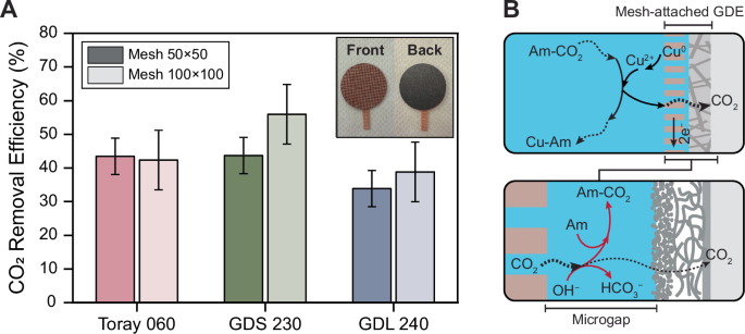
A CO2 removal efficiency of the mesh-attached GDEs with three different carbon-based substrates (Toray 060, GDS 230, and GDL 240). Two different mesh sizes, 50 × 50 and 100 × 100, were tested. The error bars show the standard deviation of three independent experiments. The inset is a photo of the mesh-attached GDE. B A schematic representation of the mesh-attached GDE, illustrating a microscale gap (microgap) between the mesh and the carbon-based substrate. Desorbed CO2 at the anode interface is reabsorbed by amine (Am) and hydroxide (OH−), leading to ineffective collection of CO2 by the gas channel located at the back of the GDE.
The results suggest a CO2 removal inefficiency of 45% to 65% from the mesh-attached GDEs. This inefficiency likely originates from two sources: (1) a parasitic oxidation reaction occurring alongside the desired oxidation of copper on the anode electrode (i.e., Cu0 → Cu2+ + 2e−), which is the primary driving force for the eventual desorption of CO2, and (2) the desorbed CO2 at the anode interface (the mesh in this case) was not effectively collected in the gas channel behind the GDE. The former can be referred to as Faradaic inefficiency, and the latter as inefficient CO2 collection. Previous studies have demonstrated that the EMAR system achieves nearly 100% Faradaic efficiency, indicating that almost all of the applied current is utilized for the intended copper redox reactions—copper oxidation at the anode and reduction at the cathode—without significant parasitic side reactions19,26,27. Therefore, it is likely that the primary source of removal inefficiency is due to inefficient collection rather than inefficient desorption.
The inefficient CO2 collection can be attributed to the presence of a microscale gap, or “microgap”, between the mesh and the carbon-based substrate, which is filled with the electrolyte. As the desorbed CO2 travels through this wetted microgap, it is partially reabsorbed into the electrolyte, either by available free amines or hydroxide ions (Fig. 2B). Since CO2 absorption by primary amines such as EDA (forming carbamate) is kinetically faster than by hydroxide (forming bicarbonate)60,61, reabsorption by amine is likely the dominant pathway, given the short distance and brief time during which CO2 traverses the electrolyte-filled microgap. Eliminating the microgap is challenging, as it is a consequence of the mechanical attachment of the mesh to the carbon-based substrate. Attempts to create a zero-gap electrode by mechanically pressing the materials at elevated pressures and temperatures were unsuccessful, as the fragility of the carbon paper resulted in its structural failure (Section S11; Supporting Information).
The relative removal efficiencies of the different carbon-based substrates can be linked to their structural and morphological characteristics. The GDL 240 substrate is coated with a carbon black microporous layer (MPL) and a polytetrafluoroethylene (PTFE) layer. Toray 060 has only a PTFE layer, while GDS 230 lacks both layers. Cross-sectional Scanning electron microscopy (SEM) images confirmed the presence of these layers (see Section S4 in the Supporting Information). These layers create resistance to CO2 transfer through the material matrix.
The differences in removal efficiencies between samples with different mesh sizes can be attributed to the variation in their thickness, which affects the travel distance and time for CO2 from desorption at the anode interface to reaching the gas channels. The thickness of the 50 × 50 mesh (228 μm) is twice that of the 100 × 100 mesh (128 μm), resulting in CO2 being exposed to the electrolyte for almost twice as long after desorption in the 50 × 50 mesh. This longer exposure increases the likelihood of CO2 reabsorption mainly by amine as described earlier.
Electrodeposited GDEs
Electrodeposited GDEs were prepared by depositing copper with specific loadings onto the three different carbon-based substrates. In general, the CO2 removal efficiency of the electrodeposited GDEs outperformed that of the mesh-attached GDEs, with several samples reaching efficiencies above 90% (Fig. 3A). Among the different carbon substrates, GDS 230 and Toray 060 showed similar efficiencies, both of which were significantly higher than that of GDL 240, regardless of the copper loading. These differences can be attributed to the structural and morphological characteristics of the substrates, as observed in the mesh-attached GDEs.
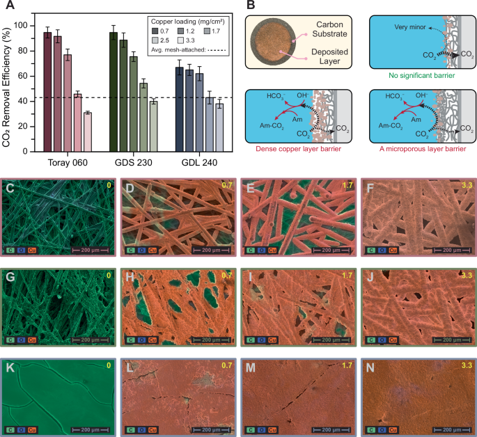
A CO2 removal efficiency of electrodeposited GDEs with three different carbon-based substrates (Toray 060, GDS 230, and GDL 240) and various copper loadings. The error bars show the standard deviation of three independent experiments. The dashed line indicates the average efficiency of the mesh-attached GDE. B Schematic illustration showing the physical barriers created by both the copper layer and the microporous layer. These barriers facilitate the reabsorption of desorbed CO2 by amine (Am) or hydroxide (OH−). (C-F) SEM images of Toray 060 with copper loadings of (C) 0, (D) 0.7, (E) 1.7, and (F) 3.3 mg/cm2. G–J SEM images of GDS 230 with copper loadings of (G) 0, (H) 0.7, (I) 1.7, and (J) 3.3 mg/cm2. K–N SEM images of GDL 240 with copper loadings of (K) 0, (L) 0.7, (M) 1.7, and (N) 3.3 mg/cm2. For all SEM images, EDS results are overlaid, with green indicating the presence of carbon, blue for oxygen, and orange for copper.
The efficiency was adversely impacted by higher copper loadings, irrespective of the substrate type. At a copper loading of 0.7 mg/cm2, Toray 060 and GDS 230 achieved efficiencies of 95%, while GDL 240 reached 67%. The efficiencies slightly decreased at a copper loading of 1.2 mg/cm2, with Toray 060 at 91%, GDS 230 at 90%, and GDL 240 at 65%. Further increases in copper loading to 1.7 mg/cm2 led to more efficiency reductions: 78% for Toray 060, 76% for GDS 230, and 62% for GDL 240. Beyond 1.7 mg/cm2, a substantial drop in efficiency was observed. At a copper loading of 2.5 mg/cm2, the efficiencies dropped to 48% for Toray 060, 55% for GDS 230, and 42% for GDL 240, nearing the average efficiency of the mesh-attached GDEs (42%). Efficiencies fell below the mesh GDE average when copper loading reached its highest at 3.3 mg/cm2 (Fig. 3A).
The microgap present in the mesh-attached GDEs was inherently eliminated in the electrodeposited GDE assembly, as the copper was directly deposited onto the surface of the carbon substrate. However, the deposited copper layer itself can act as a physical barrier to the transport of desorbed CO2 from the electrode interface to the gas channel, leading to the reabsorption of desorbed CO2, and consequently, lowering the removal efficiency. In the case of GDL 240, the MPL may also contribute to this barrier effect (Fig. 3B), which explains the lower efficiency of GDL 240 compared to Toray 060 and GDS 230, both of which lack an MPL, regardless of the copper loading.
As copper loading increases, the physical barrier effect intensifies, potentially blocking the pores on the carbon paper, as evidenced by SEM images (Fig. 3C–N). At higher copper loadings (Fig. 3F, J, and N), the surface becomes almost completely covered by the copper layer, creating significant resistance to the removal of desorbed CO2, resulting in higher rates of CO2 reabsorption and lower efficiencies. Energy dispersive X-ray spectroscopy (EDS) results for all three samples show that the green color representing the porous carbon paper fades away as it becomes covered by the copper layer. In the case of GDL 240, the surface is nearly fully covered with copper even at lower loadings (Fig. 3L). This formation of a copper layer as a physical barrier to CO2 transport explains the efficiency drop with increasing copper loading. Additional details on the SEM and EDS results can be found in Section S5 the Supporting Information.
Current density and energy consumption
In addition to CO2 removal efficiency, two other critical performance metrics were investigated: current density, which reflects the carbon capture rate, and energy consumption, which represents the energetics of the carbon capture process. As for current density, the mesh-attached GDEs outperformed the electrodeposited GDEs, likely due to the larger amount of copper available per surface area on the electrode. Among the mesh sizes, the 50 × 50 mesh exhibited better performance compared to the 100 × 100 mesh, with the highest current density achieved by the 50 × 50 mesh attached to GDS 230, reaching 184 A/m2 (Fig. 4A). For the electrodeposited GDEs, increased copper loading led to higher current densities due to the greater amount of redox-active material available for the same surface area. The highest current density for the electrodeposited GDEs was observed with the Toray 060 substrate at a copper loading of 1.7 mg/cm2, reaching 176 A/m2.
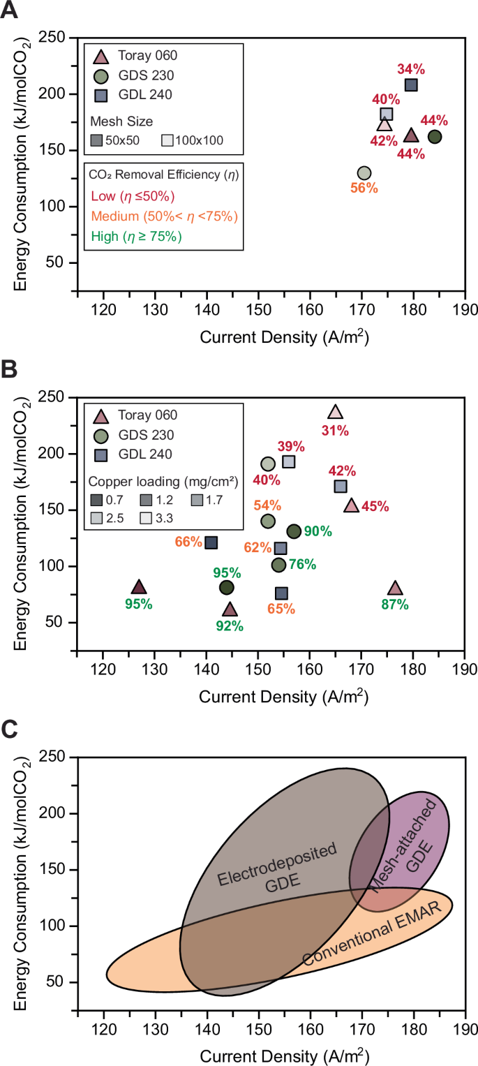
The current density and energy consumption for carbon capture using the developed membraneless EMAR system were evaluated. The corresponding CO2 removal efficiency (η) values are provided for all developed GDEs and categorized into three groups: Low (η ≤ 50%; red), Medium (50% <η < 75%; orange), and High (η ≥ 75%; green). A Performance of all mesh-attached GDE assemblies, including mesh sizes of 50 × 50 and 100 × 100. B Performance of all electrodeposited GDEs with different copper loadings. For both mesh-attached and electrodeposited GDEs, three different carbon-based substrates were used: Toray 060, GDS 230, and GDL 240. C Comparison of the membraneless EMAR system with the two different GDE configurations against the conventional EMAR in terms of current density and energy consumption.
As for energy consumption, electrodeposited GDEs generally required less energy to remove CO2 compared to the mesh-attached GDEs (Fig. 4A). Among the mesh-attached GDEs, energy consumption was highest for GDL 240, followed by Toray 060 and GDS 230, which is consistent with the removal efficiencies observed in Fig. 2. For the electrodeposited GDEs, energy consumption followed a similar trend, with higher copper loadings requiring more energy. These results highlight the critical impact of removal efficiency on the energy intensity of the carbon capture process.
Increasing the copper loading had a positive impact on current density but negatively affected both CO2 removal efficiency and energy consumption. Therefore, there is an optimal copper loading for performance. Considering the high removal efficiency (87%), high current density (176 A/m2), and low energy consumption (76 kJ/mol CO2), Toray 060 with 1.7 mg/cm2 of copper loading was identified as the most optimal GDE, exhibiting the best overall performance metrics. The performance of this GDE assembly served as the basis for the TEA discussed in Section 3.3.
The performance of the developed GDEs, both mesh-attached and electrodeposited, in terms of current density and energy consumption, was compared to the performance metrics reported for a wide range of configurations in conventional membrane-based EMAR systems (Fig. 4B). The membraneless EMAR with GDE electrodes proved competitive with conventional EMAR systems. Importantly, the introduction of these new electrodes and the substantial simplification of the process, which could potentially reduce costs, did not result in an increase in energy consumption or a reduction in current density. Additionally, the GDE configurations, particularly the electrodeposited GDEs, achieved significantly higher removal efficiencies (>90%) compared to conventional EMAR, which is typically limited to <75%37. Overall, the developed membraneless EMAR with GDE electrodes demonstrates promising performance metrics, making it a viable option for scalable electrochemical carbon capture.
Economics of the membraneless EMAR
Purchase cost contributions
TEA was performed to compare the economics of carbon capture using the developed membraneless and the conventional membrane-based EMAR. A breakdown of the purchased equipment cost (PEC) for the membraneless EMAR versus the conventional EMAR is shown in Fig. 5A and 5B, revealing the individual cost components. Due to the significantly simpler process flow diagram of the membraneless EMAR (Fig. S12 in the Supporting Information), fewer equipment purchases are required. Specifically, the absorption column and cooling tower, flash tank, and most of the pumps are eliminated. This simplification offers a clear economic advantage for the membraneless system. The electrochemical cell remains the major cost component in both systems, accounting for 78.4% in the membraneless and 80.8% in the conventional system. In the membraneless EMAR, the GDE accounts for 63.1%, while the membrane represents 55.8% of the PEC in the conventional system.
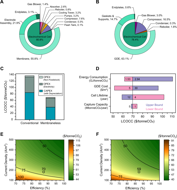
A, B Purchased equipment cost (PEC) breakdown for (A) the conventional EMAR and (B) the membraneless EMAR. The sliced pie chart illustrates the cost shares of all associated process components, while the donut chart represents the cost shares of the electrochemical cell components. C Comparison of the levelized cost of carbon capture (LCOCC) for the conventional versus membraneless EMAR. Operating expenses (OpEx) includes both non-feedstock costs (e.g., labor, on-site feedstock handling, and maintenance) and electricity, while depreciation is considered for CapEx. D Sensitivity analysis of four key parameters, showing the LCOCC at their associated lower and upper bounds. E, F Cost target analysis for the membraneless EMAR with cell lifetime of 8 years (E) and 12 years (F). The contour plot represents the LCOCC as a function of varying efficiency and current density. The lines indicate LCOCC values of $50, $75, and $100 per tonneCO2, while the circles represent the LCOCC for the developed membraneless EMAR at its current performance metrics.
Levelized cost of carbon capture
Both CapEx and operating expenses (OpEx) were considered in evaluating the LCOCC (Fig. 5C). In both systems, CapEx is the dominant factor in the levelized cost, with $38.9/tonneCO2 for the membraneless system and $85/tonneCO2 for the conventional EMAR. The primary reason for the reduced CapEx in the membraneless system is the elimination of the expensive ion-selective membrane, which is replaced by the significantly less costly carbon-based GDEs. Additional cost savings are attributed to the elimination of several process components, as discussed. The major contributor to OpEx is electricity consumption. Due to its more efficient process, the membraneless EMAR has a lower electricity cost ($28.8/tonneCO2) compared to the conventional EMAR ($47.8/tonneCO2). When combining both CapEx and OpEx, the levelized cost of CO2 capture for the membraneless EMAR drops to $69.7/tonneCO2, compared to $137/tonneCO2 for the conventional system (Fig. 5C). This substantial cost reduction makes the membraneless EMAR an attractive, cost-effective solution for carbon capture from point sources.
Sensitivity analysis
A sensitivity analysis was performed to evaluate the impacts of four key factors—energy consumption, GDE cost, cell lifetime, and capture capacity—on the levelized cost (Fig. 5D). This analysis helps identify the most critical factors for optimizing the system’s cost-effectiveness. Energy consumption had the most significant impact; increasing the energy consumption from 1.53 GJ/tonneCO2 (the minimum theoretical required energy) to 2.94 GJ/tonneCO2 (the highest energy requirement observed in Fig. 4A) led to a rise in the levelized cost from $62 to $111 per tonne CO2. The variation in GDE cost was also prominent, where a GDE cost of $5/m2 resulted in a levelized cost of $52/tonneCO2, compared to $96/tonneCO2 when the GDE price was $30/m2. An increase in cell lifetime from 4 to 12 years reduced the levelized cost from $102 to $59 per tonne of CO2. A decrease in capture capacity from 5 MtonneCO2/year (an average annual emission of coal-fired power plant) to 1 MtonneCO2/year (a typical annual emission of cement plant) did not show a significant increase in the levelized cost, reflecting the viability of the process in lower scales, inherited from its modularity.
Cost target analysis
A cost target analysis was conducted to determine the minimum CO2 removal efficiency and current density required to meet specific levelized cost targets. The removal efficiency was varied between 70% and 100%, ranges that can be effectively achieved with the developed electrodeposited GDEs (Fig. 3A), while the current density ranged from 100 to 500 A/m2. Additionally, two different lifetimes, 8 and 12 years, were considered. The 8-year cell lifetime, representing the baseline for LCOCC calculations in both conventional and membraneless EMAR systems, was selected based on the typical lifespan of conventional EMAR systems43. A 12-year cell lifetime, representing the upper bound in the sensitivity analysis, reflects the potential durability of the membraneless EMAR. Given the simplified process flow and the absence of an ion-selective membrane—known to present long-term operational challenges62,63—achieving this extended lifetime is realistic for the membraneless configuration. A similar analysis was performed for GDE costs, with the detailed results provided in Section S12.4 of the Supporting Information. The results show that achieving a levelized cost below $50 is feasible, with an operational zone bounded by efficiencies above 85% and current densities exceeding 300 A/m2. With an improvement in the cell lifetime from 8 years to 12 years, achieving a levelized cost below $50 is even more feasible, with an operational zone bounded by efficiencies above 76% and current densities exceeding 200 A/m2. The minimum required current density and efficiency for achieving levelized costs below $50 further decrease with lower GDE costs (Section S12.4; Supporting Information). Achieving capture costs below $50/tonneCO2 positions the membraneless EMAR system as a leading electrochemical solution for point-source carbon capture, making it a highly cost-effective technology.
Identifying these cost target zones is a valuable resource for guiding future research and development. Both efficiency and current density are parameters that can be systematically studied, from fundamental to practical aspects, using established scientific approaches. The plot provides a clear understanding of the extent of development needed to reach the desired cost targets. Given the high removal efficiencies already achieved with the electrodeposited GDEs (>90%), future efforts should focus on increasing the current density. To achieve this, inspiration can be drawn from other GDE-based electrochemical systems, such as air-breathing batteries, which have employed various strategies to enhance current density. For example, improving the kinetics of redox reactions at the electrode, and thereby increasing the current density, could be achieved through the use of advanced catalysts, optimizing the electrode surface area, or enhancing mass transfer rates at the gas-liquid interface59,64,65,66. Overall, the cost target analysis provides a crucial framework for setting research priorities, helping to identify the necessary improvements in efficiency and current density to achieve more economically viable carbon capture with the membraneless EMAR system.
Discussion
This study successfully developed a novel membraneless EMAR system for carbon capture, utilizing GDEs to eliminate the need for ion-selective membranes. The research was motivated by the significant contribution of membranes to the CapEx of conventional EMAR. Two types of GDE assemblies were investigated: mesh-attached and electrodeposited. Electrodeposited GDEs demonstrated superior performance over mesh-attached GDEs, achieving CO2 removal efficiencies exceeding 90% compared to 35–55% for mesh-attached GDEs. This improvement was attributed to the elimination of the microgap present in mesh-attached GDEs. This microgap caused inefficiency by allowing the reabsorption of desorbed CO2 back into the electrolyte, a problem that was effectively resolved in the electrodeposited GDEs. However, for electrodeposited GDEs, the determining factor was the copper loading; higher copper loadings resulted in lower carbon removal efficiency due to the copper deposition layer acting as a physical barrier against CO2 transport through the GDE. The relationship between copper loading and this barrier effect was confirmed by SEM and EDS analyses. Among the carbon-based substrates tested for electrodeposited GDEs, Toray 060 with an optimal copper loading of 1.7 mg/cm2 exhibited the best overall performance, achieving 87% removal efficiency, 176 A/m2 current density, and 76 kJ/molCO2 energy consumption.
TEA confirmed the economic advantages of the membraneless EMAR system, with the LCOCC dropping ~50% to $69.7/tonneCO2, compared to $137/tonneCO2 for the conventional system. This substantial cost reduction was primarily attributed to lower CapEx, particularly the elimination of expensive membranes and other process components, i.e., absorption column, pumps, and flash tank. Sensitivity analysis and cost target analysis demonstrated the feasibility of achieving carbon capture costs as low as $50/tonneCO2 with the membraneless EMAR system if the performance metrics (current density and removal efficiency) are further improved.
Therefore, future research should focus on increasing current density while maintaining high carbon removal efficiency and low energy consumption. To enhance the current density of the membraneless EMAR system, several strategies can be explored. Electrode engineering techniques, such as surface modifications through acid, plasma, or thermal treatments, can improve electrode activity and stability. Optimizing the structure of the GDE, including refining the layer configuration and adjusting porosity, can significantly enhance mass transfer efficiency. Further improvements can be achieved by optimizing the cell geometry to promote uniform current distribution and minimize energy losses. Additionally, electrolyte optimization, whether by modifying the background electrolyte composition or introducing specific additives, can play a role in increasing the current densities. However, these strategies to improve current density may involve trade-offs with other performance metrics, such as absorption kinetics, energy consumption, and Faradaic efficiency. Therefore, a systematic investigation focused on enhancing current densities while maintaining other key performance metrics is necessary.
Long-term cycling studies are also necessary to evaluate the performance stability of carbon substrates, particularly under continuous operation and varying conditions, such as fluctuating CO2 concentrations and electrolyte degradation. Investigating the durability of electrodeposited GDEs at higher copper loadings and their susceptibility to physical and chemical degradation over extended cycles is critical to ensure sustained performance. Furthermore, evaluating the resistance of the GDE to fouling, scaling, and operational stresses (e.g., mechanical stability under pressure) will provide insights into their long-term viability for industrial applications. Additionally, comprehensive optimization of electrodeposited GDEs, including pore size, porosity, and surface area, is crucial to fully understanding CO2 desorption dynamics at the electrode-electrolyte interface.
The impact of flue gas composition on the membraneless EMAR system’s performance requires further investigation. While the current study incorporated oxygen (7% O2) into the simulated flue gas to replicate real flue gas conditions, experimental results demonstrated that oxygen did not negatively impact the system’s performance, indicating oxygen tolerance. However, the influence of other trace impurities commonly present in industrial flue gases remains unaddressed and requires comprehensive evaluation before scaling up the process. In particular, sulfur oxides (SOx), such as sulfur dioxide (SO2), pose potential challenges67,68. SOx species are known to cause catalyst degradation and passivation, which could lead to electrode performance decay in the EMAR process. Moreover, trace amounts of dissolved SOx-derived species, like hydrogen sulfide ions (HS−), may react with copper ions in the electrolyte, leading to unwanted copper sulfide precipitation that could impair system operation69. A thorough assessment of SOx’s impact on both the electrodes and the electrolyte is essential to determine whether flue gas pretreatment is necessary to mitigate these effects. If required, established desulfurization techniques—such as flue gas desulfurization scrubbing, commonly implemented in power plants—can be integrated into the process with minimal disruption to the overall system design. Addressing these considerations will ensure the long-term stability and operational robustness of the membraneless EMAR system, ultimately enhancing its readiness for future large-scale implementations.
Methods
Materials
The electrolyte solution used in all experiments included the following chemicals: 0.25 M copper (II) sulfate pentahydrate (CuSO4·5H2O; 98% purity, Sigma Aldrich) as the initial source of cupric ions (Cu2+), 1 M ethylenediamine (EDA; Sigma Aldrich) as the amine absorbent, and 0.5 M sodium sulfate (Na2SO4; purity > 99.0%, Sigma Aldrich) as a background electrolyte to enhance the electrical conductivity of the solutions. All of the solutions were prepared using deionized water with a resistivity greater than 18 MΩ·cm. The chosen concentrations of cupric ions and background electrolytes were based on an optimization study, the details of which are presented in Section S2 of the Supporting Information.
Three types of carbon-based substrates were used to provide gas diffusion media for the GDEs to facilitate the removal of desorbed CO2. The employed substrates were Toray 060 (thickness 190 μm, Fuel Cell Store), GDS 230 (thickness 230 μm, Fuel Cell Store), and GDL 240 (thickness 240 μm, Fuel Cell Store). All three carbon-based substrates were made of carbon fiber paper; however, structurally, only GDL 240 was coated with carbon black as a MPL. Both Toray 060 and GDL 240 were wet-proofed with a standard 5% PTFE layer. Additional information about the substrates is provided in Section S3 of the Supporting Information.
GDE fabrication
Two different GDE assemblies were fabricated, both with a projected surface area of 3.14 cm2: mesh-attached and electrodeposited. The mesh-attached GDEs were fabricated by mechanically pressing a copper mesh (with a mesh size of 50 × 50 or 100 × 100; McMaster Carr) onto one of the three carbon-based substrates. For GDL 240, the mesh was attached to the MPL side.
The electrodeposited GDEs were prepared by electrodepositing copper from a copper bath, inspired by the established industrial copper plating process70,71. A two-electrode cell with carbon-based substrates as the cathode and a sacrificial copper anode was employed for this purpose. The electrolyte consisted of 0.25 M CuSO4 (as the copper source) and 0.5 M Na2SO4 (as the background electrolyte). To enhance bulk mass transport, the electrolyte was continuously stirred at 220 rpm. A constant current of 50 mA was applied for varying time periods (15, 22.5, 30, 45, and 60 min), resulting in copper loadings of 0.7, 1.2, 1.7, 2.5, and 3.3 mg/cm2. Copper loading was confirmed by measuring the electrode mass before and after deposition, and the measured values closely matched the theoretical values based on the charge transferred, confirming the high efficiency of the electrodeposition process. Further details on the electrodeposition experiments are provided in Section S4 of the Supporting Information.
Characterization techniques
SEM and EDS were used to study the morphological characteristics of the fabricated GDEs. Samples were prepared by cutting them into small circles (5 mm diameter) and attaching them to SEM (Axia ChemiSE, 30 kV accelerating voltage, ThermoScientific) sample holders using conductive carbon tape. All samples were examined at 200X magnification with a working distance of ~10 mm from the detectors. EDS analysis was subsequently conducted on the same samples by activating the integrated detector through the software interface. To further inspect the fabricated GDEs, cross-sectional SEM and EDS analyses were conducted by vertically placing small slices of the samples on the sample holder. The cross-sectional SEM and EDS results for the three carbon-based substrates are provided in Section S5 of the Supporting Information. These results confirmed the layer compositions and structures of the substrates used.
Electrochemical testing
A batch two-electrode cell was designed and fabricated for testing and operating the membraneless configuration of the EMAR process at the lab scale. It consisted of a main cylindrical chamber holding 4 mL of electrolyte and two side endplates having central circular notches (20 mm diameter) for CO2 absorption and desorption. The end plates also feature small inlet and outlet ports on the sides to introduce either the simulated flue gas (15% CO2, 7% O2, 78% N2) on the cathodic side or sweep water vapor on the anodic side, which facilitates the removal of CO2 bubbles from the electrode surface. More details of the developed cell are provided in Section S6 of the Supporting Information.
To conduct the desorption experiment, the electrodes were polarized at 1 V using a potentiostat (VMP-300; Biologic) for 15 min. The desorption experiments were conducted at room temperature (set at 22 °C) using the chronoamperometry technique with a potentiostat (VMP-300; Biologic), applying a potential of 1 V for 15 min. This potential was determined to be the optimal value for the operation of the process (see Section S1 in the Supporting Information). This experimental duration was also sufficient to observe steady-state current density values and stable CO2 desorption rates. This initiated the anodic reaction, leading to CO2 desorption, and the cathodic reaction, regenerating the absorbent for further CO2 absorption from the simulated flue gas. The current response of the system (I) was recorded using the built-in software (EC-Lab; Biologic), and all the experiments were conducted at room temperature (set at 22 °C). The current profiles (I vs. t) for the 15-min desorption experiments are provided in Section S7 of the Supporting Information.
CO2 removal efficiency (\(\eta\); %) was rigorously quantified by measuring the amount of CO2 collected by the anode GDE (\(\triangle {n}_{\mathrm{experimental}}\)) and comparing it to the theoretically expected desorption amount (\({\triangle n}_{\mathrm{theoretical}}\); Eq. 1). The experimental desorption was measured using an acid titration method, ensuring accurate measurement of CO2 volume by displacement in a U-shaped manometer. The purity of the desorbed CO2 was validated using gas chromatography (GC), confirming nearly 100% purity. Further details on the titration method and GC analysis are provided in Section S8 of the Supporting Information. The theoretical desorption was calculated based on the charge transferred during the experiment (Q; C) and the stoichiometric ratio of electrons to CO2, which is 1:125—meaning that the transfer of one mole of electrons theoretically results in the desorption of one mole of CO2 (Eq. 2).
$$\eta=\frac{\triangle {n}_{\mathrm{experimental}}}{{\triangle n}_{\,\mathrm{theoretical}}}\times 100$$
(1)
$${\triangle n}_{\,\mathrm{theoretical}}=\frac{Q}{F}=\frac{{It}}{F}$$
(2)
where t is the experiment time (s) and F is the Faraday constant (96,485 C/mol). To further ensure the reliability and long-term applicability of the membraneless EMAR system, the chemical stability of the electrolyte—particularly the EDA amine—was thoroughly evaluated. Both the gas and liquid phases were analyzed to detect any potential degradation products. GC analyzed the composition of the desorbed gas, while Fourier Transform Infrared (FTIR) spectroscopy was used to assess changes in the liquid phase. The results confirmed no detectable degradation products in either phase, indicating high electrolyte stability under the tested conditions. Detailed procedures and results of these analyses are provided in Section S9 of the Supporting Information.
Finally, the energy consumption for CO2 desorption (W; kJ/molCO2) was calculated as:
$$W=\frac{{\int }_{0}^{t}U\,I{dt}}{\triangle {n}_{\mathrm{experimental}}}$$
(3)
where U (V) is the applied potential across the GDE electrodes. A detailed analysis of the minimum work required for CO2 separation and the discussion regarding the importance of the second law efficiency as a standardized matrix for carbon capture techniques72 is provided in Section S10 of the Supporting Information.
Techno-economic analysis (TEA)
Process design
A TEA was conducted to compare the costs of carbon capture using the developed membraneless EMAR and a conventional membrane-based system. The membraneless EMAR operates with a simplified one-compartment configuration, combining CO2 absorption and desorption in a single electrochemical unit. This eliminates several pieces of equipment, such as the absorption column, several pumps, and a flash tank, which are necessary for conventional EMAR. The reduction in equipment results in significant simplification of the process and reduces the CapEx. Further details of the process design and flow diagrams for both systems are provided in Section S12 of the Supporting Information.
Levelized cost of carbon capture
The Levelized Cost of Carbon Capture (LCOCC) was calculated for both systems to assess their overall economic viability. The TEA model considered a hypothetical scaled-up carbon capture facility integrated with a 550 MWe coal-fired power plant based on the National Energy Technology Laboratory (NETL) reference model, with annual CO2 emissions of 3.1 Mtonne43,73. All the process and economic parameters and assumptions used for TEA are summarized in Tables S3 and S4 of Section S12 of the Supporting Information.
Capital and operating expenditures were analyzed to estimate LCOCC and identify the major cost contributors. CapEx were mainly driven by the PEC, which was divided into process and electrochemical components. The former was estimated based on sizing and data reported for an EDA-based carbon capture unit43,74, and the latter was estimated based on a scaled-up plan for the EMAR electrochemical modules. The calculated PEC for electrochemical and process equipment in both EMAR configurations are provided in Tables S6 and S8 of Section S12 of the Supporting Information. CapEx was then calculated by taking depreciation into account, using the capital recovery factor to estimate the annual depreciation costs over the plant’s lifetime, ensuring a more comprehensive estimate of the capital costs74. Further details and relevant data can be found in Table S5, and Tables S7, 8 in Section S12 of the Supporting Information. The OpEx included both feedstock and non-feedstock components. The feedstock component was directly related to the electricity required to run the system, while the non-feedstock component included costs associated with labor, on-site feedstock handling, and maintenance. The LCOCC was then calculated by combining CapEx (with depreciation) and OpEx (including both feedstock and non-feedstock components). Whenever assumptions were necessary for our analysis, we opted for conservative estimates to avoid overly optimistic projections of the LCOCC. As a result, the actual LCOCC values could potentially be lower than those reported here.
Sensitivity analysis
A sensitivity analysis was performed to examine the impact of key variables on the LCOCC. The analysis evaluated the influence of four factors: energy consumption, GDE cost, cell lifetime, and capture capacity. Energy consumption was analyzed from 1.53 to 2.94 GJ/tonneCO2, ranging from the theoretical minimum for the EMAR process to the highest experimental value observed in our study, which represents the worst-case scenario. GDE cost was evaluated from $5/m2, achievable based on prices projected by the Department of Energy (DOE)75, to $30/m2, reflecting the price range reported in the literature for similar scaled-up processes76. Cell lifetime was varied from 4 to 12 years, representing the typical range for electrochemical systems43,77. Capture capacity varied from 1 to 5 MtonneCO2/year, covering facility sizes from average cement plants to large coal power plants78. Detailed sensitivity analysis assumptions are presented in Table S10 in Section S12 of the Supporting Information.
Cost Target Analysis
A cost target analysis was performed to identify the minimum CO2 removal efficiency and current density required to achieve specific cost targets. This analysis also helped with assessing the impact of CO2 separation rate as a key parameter in TEA, which is directly related to the current density and efficiency:
$${{n}^{\circ }}_{{\mathrm{CO}}_{2}}=\frac{\eta\ I}{F}$$
(4)
where η is the CO2 removal efficiency, I is the average current density, and F is the Faraday constant. The removal efficiency was varied from 70% to 100%, and the current density ranged between 100 and 500 A/m2. The analysis also included two different lifetimes for GDEs (8 and 12 years) to provide a comprehensive understanding of how these parameters interact to affect LCOCC in different scenarios. A similar analysis was conducted for GDE costs and the results are provided in Section S12.4 of the Supporting Information. Contour lines corresponding to LCOCC values of $50, $75, and $100 per tonne of CO2 were added to the plot to highlight the operational zones required to reach these target cost levels.
Data availability
Source data are provided with this paper.
References
C. Intergovernmental Panel on Climate, Climate Change 2022-Impacts, Adaptation and Vulnerability: Working Group II Contribution to the Sixth Assessment Report of the Intergovernmental Panel on Climate Change. (Cambridge: Cambridge University Press, 2023).
Rahimi, M., Khurram, A., Hatton, T. A. & Gallant, B. Electrochemical carbon capture processes for mitigation of CO2 emissions. Chem. Soc. Rev. 51, 8676–8695 (2022).
Renfrew, S. E., Starr, D. E. & Strasser, P. Electrochemical approaches toward CO2 capture and concentration. ACS Catal. 10, 13058–13074 (2020).
Rahimi, M., Moosavi, S. M., Smit, B. & Hatton, T. A. Toward smart carbon capture with machine learning. Cell Rep. Phys. Sci. 2, 100396 (2021).
J. Newman and N. P. Balsara, Electrochemical systems. (John Wiley & Sons, 2021).
Li, X., Zhao, X., Liu, Y., Hatton, T. A. & Liu, Y. Redox-tunable Lewis bases for electrochemical carbon dioxide capture. Nat. Energy 7, 1065–1075 (2022).
Liu, Y., Ye, H.-Z., Diederichsen, K. M., Van Voorhis, T. & Hatton, T. A. Electrochemically mediated carbon dioxide separation with quinone chemistry in salt-concentrated aqueous media. Nat. Commun. 11, 2278 (2020).
Seo, H., Rahimi, M. & Hatton, T. A. Electrochemical carbon dioxide capture and release with a redox-active amine. J. Am. Chem. Soc. 144, 2164–2170 (2022).
Zhu, P. et al. Continuous carbon capture in an electrochemical solid-electrolyte reactor. Nature 618, 959–966 (2023).
Aleta, P., Refaie, A., Afshari, M., Hassan, A. & Rahimi, M. Direct ocean capture: the emergence of electrochemical processes for oceanic carbon removal. Energy Environ. Sci. 16, 4944–4967 (2023).
Digdaya, I. A., et al. A direct coupled electrochemical system for capture and conversion of CO2 from oceanwater. Nat. Commun. 11, 4412 (2020).
Jing, Y. et al. Electrochemically induced CO2 capture enabled by aqueous quinone flow chemistry. ACS Energy Lett. 9, 3526–3535 (2024).
Guo, Y., Massen-Hane, M., Endy, G. & Hatton, T. A. “Porous polymeric electrodes for electrochemical carbon dioxide capture,” Adv. Mater. 36, e2407567 (2024).
Voskian, S. & Hatton, T. A. Faradaic electro-swing reactive adsorption for CO 2 capture. Energy Environ. Sci. 12, 3530–3547 (2019).
Abdinejad, M., Seo, H., Lev Massen-Hane, M. E. & Hatton, T. A. “Oxygen-stable electrochemical CO2 capture using redox-active heterocyclic benzodithiophene quinone,” Angew. Chem. Int. Ed. 63, e202412229 (2024).
Seo, H., Nitzsche, M. P. & Hatton, T. A. Redox-mediated pH swing systems for electrochemical carbon capture. Acc. Chem. Res. 56, 3153–3164 (2023).
Rahimi, M. et al. Carbon dioxide capture using an electrochemically driven proton concentration process. Cell Rep. Phys. Sci. 1, 100033 (2020).
Rahimi, M., Catalini, G., Puccini, M. & Hatton, T. A. Bench-scale demonstration of CO2 capture with an electrochemically driven proton concentration process. RSC Adv. 10, 16832–16843 (2020).
Afshari, M., Refaie, A., Aleta, P., Hassan, A. & Rahimi, M. A Vanadium Redox Flow Process for Carbon Capture and Energy Storage. ACS EST Eng. 5, 1099–1110 (2025).
Jin, S., Wu, M., Jing, Y., Gordon, R. G. & Aziz, M. J. Low energy carbon capture via electrochemically induced pH swing with electrochemical rebalancing. Nat. Commun. 13, 1–11 (2022).
Xu, Z., et al. Enhancing electrochemical carbon dioxide capture with supercapacitors. Nat. Commun. 15, 7851 (2024).
Bilal, M., Li, J., Guo, H. & Landskron, K. “High-voltage supercapacitive swing adsorption of carbon dioxide,”. Small 19, 2207834 (2023).
Bilal, M., Li, J. & Landskron, K. Enhancing supercapacitive swing adsorption of CO2 with advanced activated carbon electrodes. Adv. Sustain. Syst. 7, 2300250 (2023).
Stern, M. C., Simeon, F., Herzog, H. & Hatton, T. A. Post-combustion carbon dioxide capture using electrochemically mediated amine regeneration. Energy Environ. Sci. 6, 2505–2517 (2013).
Rahimi, M. et al. An electrochemically mediated amine regeneration process with a mixed absorbent for postcombustion CO2 capture. Environ. Sci. Technol. 54, 8999–9007 (2020).
Wang, M. et al. Flue gas CO2 capture via electrochemically mediated amine regeneration: System design and performance. Appl. Energy 255, 113879 (2019).
Khurram, A., He, M. & Gallant, B. M. Tailoring the discharge reaction in Li-CO2 batteries through incorporation of CO2 capture chemistry. Joule 2, 2649–2666 (2018).
Kuo, F.-Y., Jerng, S. E. & Gallant, B. M. Dual salt cation-swing process for electrochemical CO2 separation. ACS Cent. Sci. 9, 1750–1757 (2023).
Hassan, A., et al. “Reviving the absorbent chemistry of electrochemically mediated amine regeneration for improved point source carbon capture,”. Chem. Eng. J. 484, 149566 (2024).
Mao, Y. et al. Stability improvement of the advanced electrochemical CO2 capture process with high-capacity polyamine solvents. Appl. Energy 369, 123597 (2024).
Wu, X. et al. Systematic study of an energy efficient MEA-based electrochemical CO2 capture process: from mechanism to practical application. Appl. Energy 327, 120014 (2022).
Wu, X. et al. Comparative performance evaluation of absorbents for the electrowinning-coupled competitive separation CO2 capture process. ACS Sustain. Chem. Eng. 12, 2080–2091 (2024).
Rahimi, M., Zucchelli, F., Puccini, M. & Hatton, T. A. lan Improved CO2 capture performance of electrochemically mediated amine regeneration processes with ionic surfactant additives. ACS Appl. Energy Mater. 3, 10823–10830 (2020).
Li, Z. et al. Potassium β–alanine–A promising agent for reducing carbon capture cost via electrochemically mediated amine regeneration. Sep. Purif. Technol. 334, 125984 (2024). p.
Wang, C. et al. Electrowinning-coupled CO2 capture with energy-efficient absorbent regeneration: Towards practical application. Chem. Eng. J. 427, 131981 (2022).
de Meyer, F., Bignaud, C. & Poulain, B. Selective electrochemical regeneration of aqueous amine solutions to capture CO2 and to convert H2S into hydrogen and solid sulfur. Appl. Sci. 11, 9851 (2021).
Wang, M., Hariharan, S., Shaw, R. A. & Hatton, T. A. Energetics of electrochemically mediated amine regeneration process for flue gas CO2 capture. Int. J. Greenh. Gas. Control 82, 48–58 (2019).
Hasanzadeh, A. et al. Electrochemically mediated amine regeneration and proton concentration modulation processes for flue gas CO2 capture: comparison and artificial intelligence-based optimization. J. CO2 Util.67, 102306 (2023).
Hasanzadeh, A., Mehrara, M., Irani, M., Chitsaz, A. & Parham, K. An innovative biomass-fueled gas turbine-ORC system equipped with electrochemically mediated amine regeneration (EMAR) for CO2 capture. J. CO2 Util.68, 102365 (2023).
Fan, H. et al. Combined experimental and computational study for the electrode process of electrochemically mediated amine regeneration (EMAR) CO2 capture. Appl. Energy 350, 121771 (2023).
Fan, H. et al. Performance enhancement of desorption reactor in the electrochemically mediated amine regeneration CO2 capture process: Thru modelling, simulation, and optimization. Appl. Energy 376, 124287 (2024).
Hasanzadeh, A., Chitsaz, A., Khalilian, M., Rosen, M. A. & Mehr, A. S. Experimental evaluation of electrochemically mediated amine regeneration integrated with amine thermal swing for CO2 capture at optimized desorption temperatures. J. CO2 Util.87, 102922 (2024).
Wang, M., Shaw, R., Gencer, E. & Hatton, T. A. Technoeconomic analysis of the electrochemically mediated amine regeneration CO2 capture process. Ind. Eng. Chem. Res. 59, 14085–14095 (2020).
Thiam, B. G. & Vaudreuil, S. Recent membranes for vanadium redox flow batteries. J. Electrochem. Soc. 168, 070553 (2021).
Wang, Y., Wang, C.-Y. & Chen, K. S. Elucidating differences between carbon paper and carbon cloth in polymer electrolyte fuel cells. Electrochim. Acta 52, 3965–3975 (2007).
Zhu, J., Pedersen, A., Kellner, S., Hunter, R. D. & Barrio, J. Impact of ionomers on porous Fe-N-C catalysts for alkaline oxygen reduction in gas diffusion electrodes. Commun. Chem. 8, 27 (2025).
Kang, J.-H. et al. Lithium–air batteries: air-breathing challenges and perspective. ACS Nano 14, 14549–14578 (2020).
Wong, R. A. et al. Critically examining the role of nanocatalysts in Li–O2 batteries: viability toward suppression of recharge overpotential, rechargeability, and cyclability. ACS Energy Lett. 3, 592–597 (2018).
Elia, G. A. et al. An advanced lithium–air battery exploiting an ionic liquid-based electrolyte. Nano Lett. 14, 6572–6577 (2014).
Higgins, D., Hahn, C., Xiang, C., Jaramillo, T. F. & Weber, A. Z. Gas-diffusion electrodes for carbon dioxide reduction: a new paradigm. ACS Energy Lett. 4, 317–324 (2019).
Weng, L.-C., Bell, A. T. & Weber, A. Z. Modeling gas-diffusion electrodes for CO2 reduction. Phys. Chem. Chem. Phys. 20, 16973–16984 (2018).
Sun, M., Cheng, J. & Yamauchi, M. Gas diffusion enhanced electrode with ultrathin superhydrophobic macropore structure for acidic CO2 electroreduction. Nat. Commun. 15, 491 (2024).
Duan, J., et al. Aqueous thermogalvanic cells with a high Seebeck coefficient for low-grade heat harvest. Nat. Commun. 9, 5146 (2018).
Dupont, M. F., MacFarlane, D. R. & Pringle, J. M. Thermo-electrochemical cells for waste heat harvesting—progress and perspectives. Chem. Commun. 53, 6288–6302 (2017).
Logan, B. E. et al. Microbial fuel cells: methodology and technology. Environ. Sci. Technol. 40, 5181–5192 (2006).
Cui, H. et al. Microbial fuel cell-assisted composting shows stronger capacity to immobilize phosphorus: Emphasized on bacterial structures and functional enzymes. Bioresour. Technol. 413, 131456 (2024).
Buckingham, M. A., Laws, K., Li, H., Kuang, Y. & Aldous, L. Thermogalvanic cells demonstrate inherent physiochemical limitations in redox-active electrolytes at water-in-salt concentrations. Cell Rep. Phys. Sci. 2, 100510 (2021).
Hadermann, A. F. Electrochemical concentration cells. Science 197, 598–599 (1977).
Lees, E. W., Mowbray, B. A., Parlane, F. G. & Berlinguette, C. P. Gas diffusion electrodes and membranes for CO2 reduction electrolysers. Nat. Rev. Mater. 7, 55–64 (2022).
Fu, L. et al. Research progress on CO2 capture and utilization technology. J. CO2 Util66, 102260 (2022).
Chai, S. Y. W., Ngu, L. H. & How, B. S. Review of carbon capture absorbents for CO2 utilization. Greenh. Gases: Sci. Technol. 12, 394–427 (2022).
Hickner, M. A., Herring, A. M. & Coughlin, E. B. Anion exchange membranes: current status and moving forward. J. Polym. Sci. Part B: Polym. Phys. 51, 1727–1735 (2013).
Salvatore, D. A. et al. Designing anion exchange membranes for CO2 electrolysers. Nat. Energy 6, 339–348 (2021).
Nguyen, T. N. & Dinh, C.-T. Gas diffusion electrode design for electrochemical carbon dioxide reduction. Chem. Soc. Rev. 49, 7488–7504 (2020).
Higgins, D., Hahn, C., Xiang, C., Jaramillo, T. F. & Weber, A. Z. Gas-diffusion electrodes for carbon dioxide reduction: a new paradigm. ACS Energy Lett. 4, 317–324 (2018).
Wang, M. Zhang, J. Kellner, S. Stephens, I. and Titirici, M.-M. “Enhanced ORR performance with biomass-derived freestanding catalyst layers: advancing mass transport in gas diffusion electrodes,” Journal of Materials Chemistry A https:/doi.org/10.1039/D4TA03864A (2024).
Khatri, R. A., Chuang, S. S. C., Soong, Y. & Gray, M. Thermal and chemical stability of regenerable solid amine sorbent for CO2 capture. Energy Fuels 20, 1514–1520 (2006).
Rao, A. B. & Rubin, E. S. A technical, economic, and environmental assessment of amine-based CO2 capture technology for power plant greenhouse gas control. Environ. Sci. Technol. 36, 4467–4475 (2002).
Estay, H., Barros, L. & Troncoso, E. “Metal sulfide precipitation: recent breakthroughs and future outlooks,”. Minerals 11, 1385 (2021).
Dow, W.-P. & Liu, C.-W. Evaluating the filling performance of a copper plating formula using a simple galvanostat method. J. Electrochem. Soc. 153, C190 (2006).
Rahimi, M. et al. Removal of copper from water using a thermally regenerative electrodeposition battery. J. Hazard. Mater. 322, 551–556 (2017).
Boualavong, J., Gorski, C. A. & Liu, Y. “Translatable reporting of energy demand and rates in electrochemical carbon capture,”. iScience 28, 111781 (2025).
Ramezan, M. et al. Carbon dioxide capture from existing coal-fired power plants, National Energy Technology Laboratory. DOE/NETL Rep. 401, 110907 (2007).
M. S. Peters, K. D. Timmerhaus, and R. E. West, Plant design and economics for chemical engineers. (McGraw-Hill, New York, 2003).
B. D. James, J. M. Huya-Kouadio, C. Houchins, and D. A. DeSantis, Mass production cost estimation of direct H2 PEM fuel cell systems for transportation applications. Update, report by Strategic Analysis, Inc., under Award Number DE-EE0007600 for the US Department of Energy, https://www.energy.gov/sites/prod/files/2019/12/f70/fcto-sa-2018-transportation-fuel-cell-cost-analysis.pdf (2018).
Minke, C., Kunz, U. & Turek, T. Carbon felt and carbon fiber-A techno-economic assessment of felt electrodes for redox flow battery applications. J. Power Sources 342, 116–124 (2017). pp.
Prykhodko, Y., Fatyeyeva, K., Hespel, L. & Marais, S. Progress in hybrid composite Nafion®-based membranes for proton exchange fuel cell application. Chem. Eng. J. 409, 127329 (2021). p.
Ali, M., Saidur, R. & Hossain, M. A review on emission analysis in cement industries. Renew. Sustain. Energy Rev. 15, 2252–2261 (2011).
Acknowledgments
Dr. Rahimi acknowledges the support from the NSF CAREER (Award #: 2338664), and the University of Houston High Priority Area Research Seed Grant (Award #: I0511686). Additionally, the authors acknowledge the support from the Department of Energy (DOE; Award #: DE-FE-0032408) and the Texas Hazardous Waste Research Center (Award #: 000188334).
Ethics declarations
Competing interests
M.R. and A.H. are listed as inventors on a patent application filed by the University of Houston that pertains to this work. M.A. declares no competing interests.
Peer review
Peer review information
Nature Communications thanks Mahinder Ramdin, and the other, anonymous, reviewers for their contribution to the peer review of this work. A peer review file is available.
Additional information
Publisher’s note Springer Nature remains neutral with regard to jurisdictional claims in published maps and institutional affiliations.
Supplementary information
Rights and permissions
Open Access This article is licensed under a Creative Commons Attribution-NonCommercial-NoDerivatives 4.0 International License, which permits any non-commercial use, sharing, distribution and reproduction in any medium or format, as long as you give appropriate credit to the original author(s) and the source, provide a link to the Creative Commons licence, and indicate if you modified the licensed material. You do not have permission under this licence to share adapted material derived from this article or parts of it. The images or other third party material in this article are included in the article’s Creative Commons licence, unless indicated otherwise in a credit line to the material. If material is not included in the article’s Creative Commons licence and your intended use is not permitted by statutory regulation or exceeds the permitted use, you will need to obtain permission directly from the copyright holder. To view a copy of this licence, visit http://creativecommons.org/licenses/by-nc-nd/4.0/.
About this article
Cite this article
Hassan, A., Afshari, M. & Rahimi, M. A Membraneless Electrochemically Mediated Amine Regeneration for Carbon Capture. Nat Commun 16, 6333 (2025). https://doi.org/10.1038/s41467-025-61525-3
Received: 19 November 2024
Accepted: 23 June 2025
Published: 09 July 2025
DOI: https://doi.org/10.1038/s41467-025-61525-3