.png)


When you open a website or call an API, your request might travel through a dozen different routers, jump across your ISP’s backbone, and land in a massive data center on the other side of the world. But how do all these different networks (Wi-Fi, fiber, 5G, etc) agree on a single way to move your data?
In the last article, we talked about the different layers of the modern Internet. In this one, we’ll dive into the first “important“ one: The Internet Layer. This is the layer that makes the Internet truly possible.
We’ll be using the RFC 791 - Internet Protocol written in 1981, as our guide, which is the blueprint still used to move every packet today. We’ll explore why this layer was created, what problems it solved, and how it works under the hood.
So, let’s get started!
Imagine the world in the 1970s: The U.S military had ARPANET, universities ran their own time-sharing networks, companies were experimenting with Ethernet LANs in their offices, satellites were carrying experimental networks like SATNET. Each of these systems worked fine on its own, but none of them could communicate with each other.
Now imagine if we could connect all of them together, so that any machine on any network could communicate with any other machine anywhere. That’s the vision that gave birth to the Internet Layer.
Connecting all these different networks is easier said than done. We can’t just wire them together and expect them to work. They use completely different protocols and are full of technical mismatches. Specifically, we run into the following problems:
Addressing: Each network has its own way of identifying machines. Ethernet uses MAC addresses, SATNET had terminal IDs, ARPANET had host numbers. None of these systems talk the same language.
Packet Size (MTU): One network might allow 1000-byte packets, while another only 500. How do we make sure our data can pass through without getting chopped in half?
Routing: Even if we solve addressing and size, after the packet leaves our machine, how does it know which path to take across all these networks to reach the right destination?
This is where the Internet Protocol (IP) comes into the picture. Look at the following section from RFC 791:
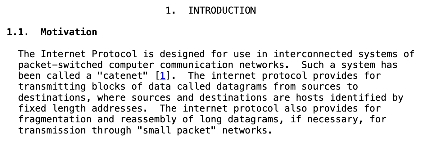
This means the following:
IP transmits data in blocks called datagrams.
Every host is identified by a fixed-length address (now called an IP address).
IP supports fragmentation and reassembly, so even if a datagram is too big for one network, it can be split into smaller pieces and put together at the destination.
Once we know the problems, it is generally a good idea to define the scope: what should the Internet Protocol solve and what it should not? Look at the following section from RFC 791:
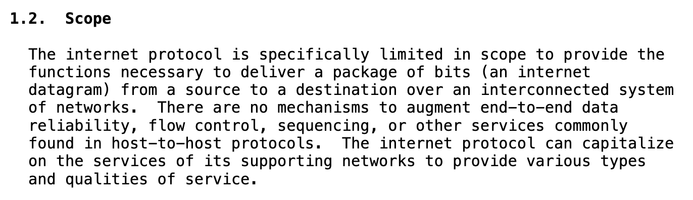
This means IP can:
Deliver a package of bits (a datagram) from a source to a destination.
Route that datagram across multiple connected networks.
But IP does NOT provide:
Reliability: data might arrive corrupted or not at all.
Sequencing: data might arrive out of order.
Duplication control: data might arrive more than once.
Flow control: IP doesn’t slow down fast senders or protect slow receivers from being overwhelmed.
Why IP is so limited?
Keeping it simple makes it universal - it can run over Ethernet, radio, satellite, and anything else.
Complexity is pushed to the edges (end hosts and applications) - the end-to-end principle.
This simplicity is exactly why the internet scaled from a few dozen machines to billions.
The end-to-end (E2E) principle is a design principle in computer networking that requires application-specific features (such as reliability and security) to be implemented in the communicating end nodes of the network, instead of in the network itself.
Let’s understand the workings of the Internet Protocol.
An Internet datagram has two main portions:
Header: meta-information about the datagram, used by IP to deliver it.
Data: the payload that needs to be sent from source to destination.
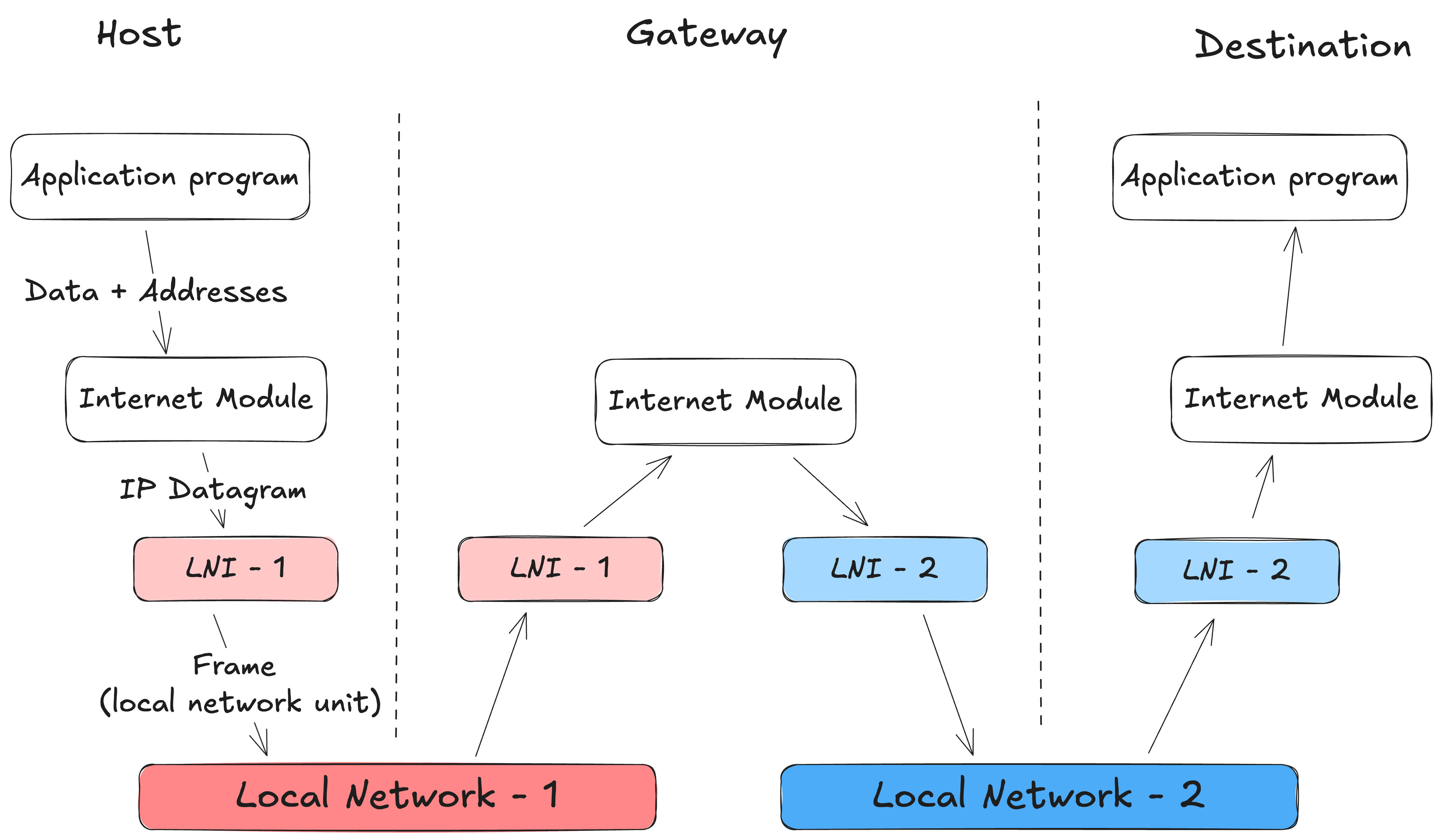
Host-to-host protocols (like TCP) hand their data (e.g, a TCP segment) to the Internet module. The TCP module also provides source and destination addresses and other parameters. The internet module then wraps this into an Internet datagram.
Next, the Internet module calls the local network interface (Ethernet, Wi-Fi, ARPANET, etc) to actually transmit the datagram. The local network interface derives the right logical address from the Internet address, add its own headers, and create its own unit of transmission.
This unit is delivered to the next machine. If the destination is on the same network, it’s the final host. If not, it usually goes through a gateway (what we now call a router) - a machine whose job is to forward datagram toward other networks.
From there, the datagram may cross multiple gateways and multiple underlying networks, each time being stripped of its local frame and wrapped in a new one for the next hop. But through all of this, the IP datagram itself remains intact, carrying the same source and destination addresses until it finally arrives at the destination host.
Following figure shows a visualisation of the process, while transmitting data where one intermediate gateway is involved (inspired from the ASCII figure in RFC 791):
Internet Protocol version 4 (IPv4) is the original and still the most widely used version of IP. This is the version defined in RFC 791, that we’ve been referring to. An IPv4 datagram consists of a header, which carries control information like source and destination addresses, and a payload, which carries the actual data from higher-layer protocols like TCP or UDP.
The datagram always starts with the header followed by raw bytes of the payload. Let’s look at the structure of its header:
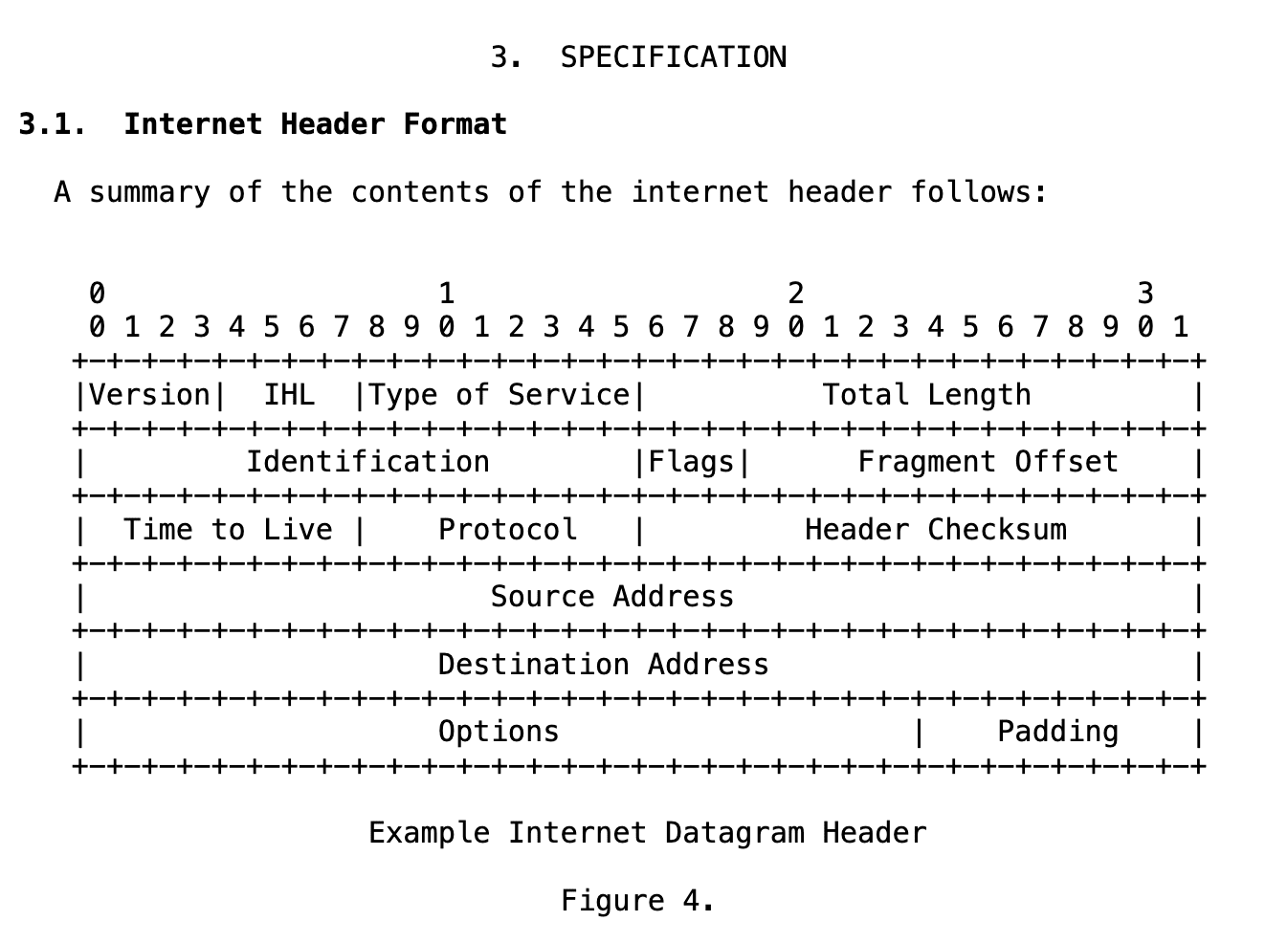
There are many interesting fields in the datagram header, and I encourage you to explore them in RFC 791 if you’re curious. But only some are still relevant or widely used today. Let’s look at the most important ones:
TTL indicates the maximum time the datagram is allowed to remain in the internet system. Each router (or host) that processes a datagram must decrease the TTL by at least 1. If the value reaches 0, the datagram is destroyed. The intention is to prevent undeliverable datagrams from circulating forever (for example, in routing loops).
Note: TTL was originally defined in seconds, but since routers process packets much faster than that, in practice it is universally treated as a maximum hop count today.
This field indicates the next-level protocol used for the data portion of the datagram. For example: a value of 6 corresponds to TCP.
The full mapping of values to protocols is maintained by Internet Assigned Numbers Authority (IANA), and can be found here.
IP does not provide error detection or data integrity checks for the payload, but it does provide a method to verify whether the header has been corrupted. This is done by using a checksum of the header.
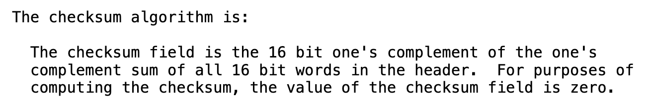
Since some header fields change at every hop (e.g., time to live), the checksum is recomputed and verified by each router that processes the datagram.
Addressing and routing are the core functions that make the Internet work. RFC 791 states that “a distinction is made between names, addresses, and routes.“
Name: indicates what we seek (hostname like www.google.com).
Address: indicates where it is (IP address like 8.8.8.8 for Google’s DNS).
Route: indicates how to get there.
Mapping of names to addresses is done by higher-level protocols like DNS. Addressing and routing happens at the Internet layer.
An IPv4 address is a unique 32-bit integer, usually written in the dot-decimal notation, which consists of 4 octets (8-bit integers) expressed individually in decimal numbers and separated by periods.
For example:
192.168.1.1
Each machine on the internet needs a unique IP address to communicate (well not really - we started running out of IP addresses pretty fast so we use techniques like NAT; more on that later).
Originally (in RFC 791), we had classful addressing. The first few bits of the address determined its “class”:
Class A: very large networks (~16 million hosts each)
Class B: medium networks (~65k hosts each)
Class C: small networks (256 hosts)
This turned out to be very wasteful. A company that needed 300 addresses, for example, couldn’t fit in Class C, so it had to waste an entire Class B block.
To fix this, the modern Internet uses CIDR (Classless Inter-Domain Routing) introduced in RFC 1519. CIDR drops the rigid class boundaries and instead uses a prefix length (written as /N) to indicate how many bits of the 32-bit address represent the network.
For example:
192.168.1.22/24 → the first 24 bits (192.168.1) define the network, the last 8 bits identify the host.
10.0.0.0/16 → the first 16 bits (10.0) define the network, the last 16 bits identify the host.
This flexibility makes it possible to allocate networks that are “just the right size“ and to aggregate blocks into larger ones, keeping the global routing system scalable.
If this feels a little abstract, don’t worry. This will get much clearer once we see how routing works in the next section.
To transmit a datagram from a source to a destination, devices first use their underlying local network to hand the datagram to a router. The router then decides where to send it next - this is called the next hop. From there, the datagram travels from router to router, until it finally reaches the destination host’s local network, where it can be delivered directly.
The decision of where to send the datagram next is done through routing tables. A routing table is a set of rules that match destination addresses to the best possible path:
A directly connected network
A specific next-hop router
A default route when nothing else fits
Example: Routing Table on your computer
Destination Gateway Interface 192.168.1.0/24 0.0.0.0 wlan0 127.0.0.0/8 0.0.0.0 lo 0.0.0.0/0 192.168.1.1 wlan0192.168.1.0/24 → any address starting with 192.168.1.* is local, so send directly on Wi-Fi (wlan0).
127.0.0.0/8 → any address starting with 127.*.*.* is loopback, so send it back to self (lo).
0.0.0.0/0 → the default route: anything else goes to the gateway 192.168.1.1.
Example: Routing Table on your home router
Destination Next Hop Interface 10.1.1.0/24 0.0.0.0 eth0 (directly connected) 10.2.2.0/24 0.0.0.0 eth1 (directly connected) 10.3.0.0/16 10.2.2.2 eth1 (via another router) 0.0.0.0/0 203.0.113.1 eth2 (default route to ISP)10.1.1.0/24 → any address starting with 10.1.1.* is directly connected, so send it out eth0.
10.2.2.0/24 → any address starting with 10.2.2.* is directly connected, so send it out eth1.
10.3.3.0/16 → any address starting with 10.3.*.* is not directly reachable, so forward it to the next hop 10.2.2.2 via eth1.
0.0.0.0/0 → the default route: anything else goes to the ISP at 203.0.113.1.
Notice how /16 covers a much larger range than /24. Instead of only 10.3.3.*, it matches all addresses in 10.3.*.*. This flexibility is what makes CIDR powerful.
Note:
0.0.0.0 as the gateway/next hop means no gateway needed - the destination is directly reachable.
0.0.0.0/0 in the destination column means default route - the catch-all path when no other rule matches.
Imagine Alice wants to send a packet to Bob.
Alice’s IP (Source host): 192.168.1.10
Bob’s IP (Destination host): 172.16.0.20
Here’s what it looks like when two routers are involved:
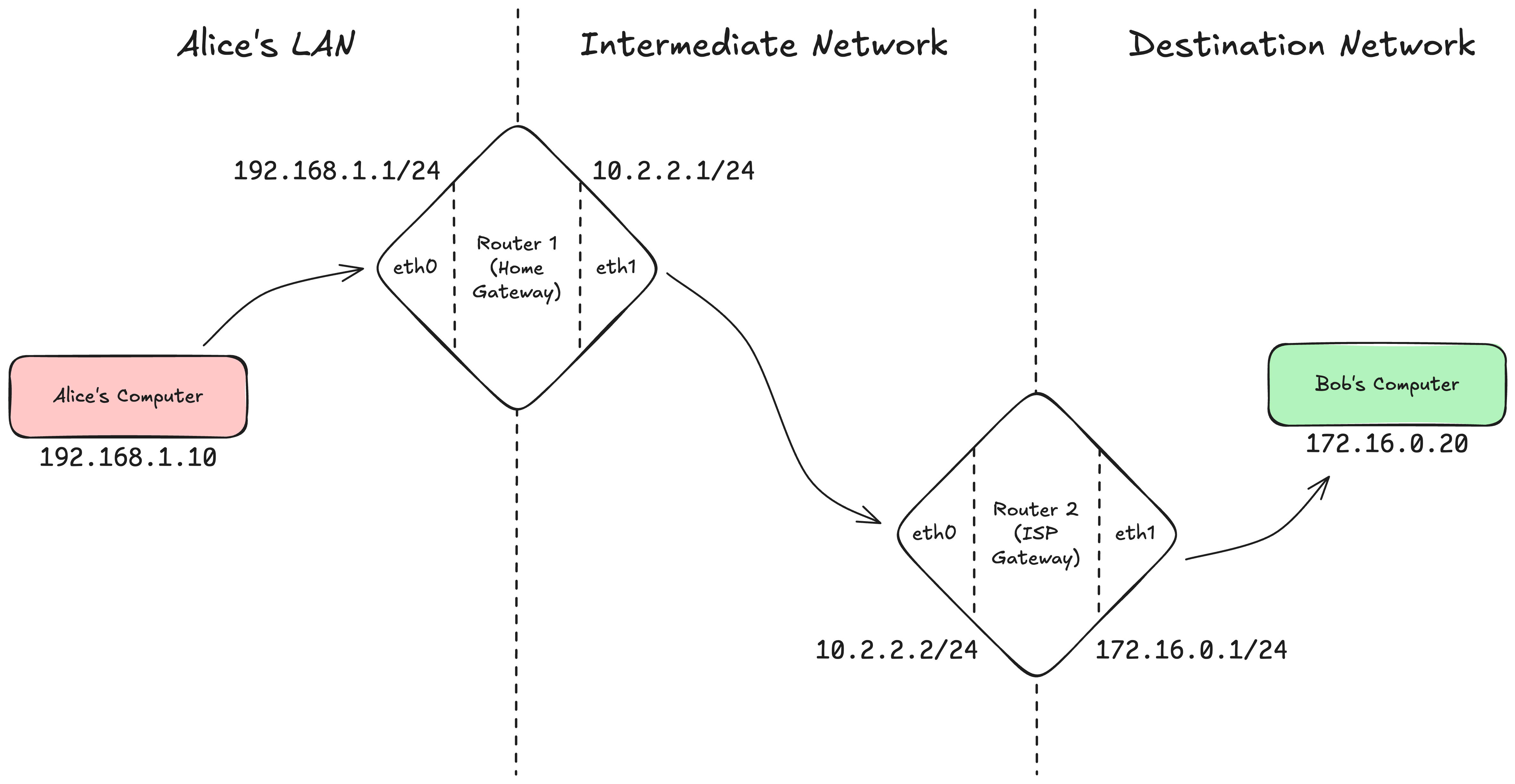
Step 1:
Alice’s laptop checks the routing table.
Destination address is not in local subnet 192.168.1.0/24.
So it forwards the datagram to default gateway, Router 1 (192.168.1.1).
Step 2:
Router 1 receives the datagram.
It checks destination (172.16.0.20) against the routing table.
Finds: 172.16.0.0/24 → next hop 10.2.2.2 (Router 2).
It forwards the datagram out its upstream interface (eth1, toward the next network).
Step 3:
Router 2 receives the datagram.
It checks destination (172.16.0.20) against the routing table.
Finds 172.16.0.0/24 → directly connected on eth1.
Forwards the datagram onto that subnet.
Step 4:
Bob’s computer (172.16.0.20) receives the datagram.
It sees the destination matches its own IP, and passes the payload up to the right transport protocol (TCP/UDP).
Based on our understanding (and taking inspiration from this wiki), here’s a simplified view of the IP forwarding algorithm:
Given a destination IP address D: if (D belongs to a directly connected network): Deliver the datagram to D over that interface; else if (The routing table contains a route for D): Forward the datagram to the next hop listed in that entry; else if (a default route exists): Forward the datagram to the default next hop; else: Drop the datagram and (optionally) send an ICMP error back;So far so good. But here’s a question:
What happens when two different routing table entries both match the destination?
For example, imagine this router’s table:
Destination Next Hop Interface 10.1.0.0/16 10.3.3.3 eth0 (via another router) 10.1.2.0/24 10.3.3.4 eth1 (via another router) 0.0.0.0/0 203.0.113.1 eth2 (default route to ISP)Now suppose a datagram arrives with destination address 10.1.2.42:
It matches both 10.1.0.0/16 and 10.1.2.0/24.
Which route should the router pick?
This is where the longest prefix match rules comes in:
Between two matches, the route with the more specific prefix (i.e., the longer subnet mask) is chosen.
In this case, /24 is more specific than /16, so the router forwards the datagram to the next hop 10.3.3.4 via eth1.
This rule keeps routing unambiguous and efficient, especially on the global internet where overlapping prefixes are common.
In practice, routers also consider additional factors when choosing between multiple matching routes:
If there are multiple routes with the same prefix-length (subnet mask), the one with the lowest metric (cost) is preferred.
If there are multiple default routes, the metric again decides which to one to use.
If there are multiple routes with the same prefix length and the same metric, the router may use Equal Cost Multi-Path Routing (ECMP) to forward traffic across more than one path.
An IPv4 address is a 32-bit integer, which gives us about ~4.3 billion unique addresses. That might seem like plenty, but in reality it’s not: everyone now has multiple devices (laptops, mobiles, TVs, even watches) and companies run hundreds of thousands of servers. The address space runs out fast.
We noticed this problem quite early, and we created several workarounds. One of the most widely used is Network Address Translation (NAT).
NAT is a method used by routers to modify the IP addresses inside packets as they pass between private networks and the public Internet.
NAT essentially works by hiding entire private networks behind a single router. This router is the only device visible on the public Internet.
To make this work, we carved out special private IP ranges that are never routed on the public Internet:
192.168.x.x
10.x.x.x
172.16.x.x - 172.31.x.x
These can be reused in every home, office, or datacenter. Only the router itself needs a unique public IP.
Imagine you and your neighbour both have Internet connections with separate routers.
Your home:
Router has:
192.168.1.1/24 for your private Wi-Fi network.
203.0.113.1 as its public Internet address.
Your 20 devices get IPs from 192.168.1.2 - 192.168.1.21
Your neighbour’s home:
Router has:
192.168.1.1/24 for their private Wi-Fi network.
203.0.113.2 as its public Internet address.
Their 50 devices get IPs from 192.168.1.2 - 192.168.1.51
Even though both homes use the same exact private IP range, there’s no conflict - because those addresses never leave the home network. On the public Internet, only the router’s public IPs (203.0.113.1 & 203.0.113.2) matter.
When a device inside a private network sends a datagram to the internet, the router rewrites the source address from the private IP to its own public IP.
Example:
Your laptop wants to connect to Facebook’s server.
Original Datagram:
Source: 192.168.1.2
Destination: 69.63.176.13 (Facebook)
Your laptop sends this datagram to your router. 192.168.1.2 is a private address, it can’t go out on the Internet. The router replaces the source with its own public IP before forwarding.
Translated Datagram:
Source: 203.0.113.1 (router’s public IP)
Destination: 69.63.176.13
Now, when Facebook replies, it sends the response back to 203.0.113.1 - your router. The router then forwards the reply to the right device.
But wait - when Facebook sends the response back to 203.0.113.1, how does the router know which private device (out of maybe 20 at home) should receive it?
This is where Port Address Translation (PAT) comes in, sometimes called NAT overload.
Before we understand PAT, we need to understand what a port is.
A port is a 16-bit number (0 - 65535) used at the transport layer to identify which application on a machine a packet belongs to.
For example:
80 → HTTP
443 → HTTPS
A browser connecting out might use a temporary port like 51000.
This way, even if multiple applications are running on the same IP address, the operating system can tell their connections apart.
Port are a transport layer concept, and we’ll look into them in detail in the transport layer article. For now, just keep in mind: they let us distinguish different conversations on the same IP.
Routers use the same trick. With PAT, the routers doesn’t just rewrite the IP address - it also rewrites the source port number and keeps a mapping in its NAT table.
Example:
Your laptop and your phone both connect to Facebook the same time.
Laptop’s original datagram:
Source: 192.168.1.2:51000
Destination: 69.63.176.13:443
Phone’s original datagram:
Source: 192.168.1.3:51000
Destination: 69.63.176.13:443
Both use the same destination and even the same ephemeral port. If the router only rewrote the IP, it wouldn’t know which reply belonged to which device.
So the router rewrites both the IP and the port:
Laptop’s translated datagram:
Source: 203.0.113.1:62001
Destination: 69.63.176.13:443
NAT table entry: 203.0.113.1:62001 → 192.168.1.2:51000
Phone’s translated datagram:
Source: 203.0.113.1:62002
Destination: 69.63.176.13:443
NAT table entry: 203.0.113.1:62002 → 192.168.1.3:51000
When Facebook replies:
203.0.113.1:62001 → router forwards to laptop.
203.0.113.1:62002 → router forwards to phone.
This works because the router looks at the protocol field in the IP header (TCP/UDP) to know where to find the port numbers in the transport layer header, and then re-writes them accordingly.
Note: with PAT, routers don’t just operate at the Internet Layer anymore - they also need to look into the transport layer headers (TCP/UDP) to read and rewrite port numbers. This breaks the traditional “clean layering“ of the internet, but it’s a practical necessity that made IPv4 scale far beyond its original limits.
What we have discussed so far is still how the Internet works today - but IPv4 comes with its own set of problems:
IPv4 has a 32-bit address space, about ~4.3 billion unique addresses. This seemed huge in the 1980s, but in 1990s, with PCs, mobile phones, and later IoT, it was clear this wasn’t enough. Workarounds like NAT, CIDR, DHCP helped stretch it, but at the cost of added complexity.
NAT devices maintain state and hide multiple hosts behind a single public IP. This breaks the end-to-end principle: unlike phone calls, you can’t just connect to any host on the Internet, because most devices don’t even have a public IP address.
NAT fit the client-server era of the 1990s, where clients sat behind NAT and connected to public servers (like Google). That model works fine because the server side is always publicly reachable.
But NAT complicates peer-to-peer applications. Things like VoIP, video calls, online gaming, and file sharing need direct host-to-host connections - which isn’t possible without workarounds. Protocols like STUN, TURN, and ICE (used in WebRTC, Zoom, etc.) exist purely to bypass NAT or relay traffic through servers. This adds operational complexity and breaks the simplicity of the original Internet design.
IPv4 headers have variable length and optional fields (e.g., fragmentation, options). Routers must do extra work at each hop - fragmentation decisions, checksum recalculation, parsing options. With today’s high bandwidth and massive traffic volumes, this overhead is inefficient.
IPv6 is a new version of the Internet Protocol (IP) designed as the successor to IPv4. We will use RFC 8200 as our guide to understand IPv6. The biggest changes come in two areas: addressing and header format.
IPv6 addresses are 128-bit identifiers, giving us about 3.4 x 1038 unique addresses (that’s more than the number of stars in the observable universe!). This enormous space means every device can now have a globally unique IP address, removing the need for NAT.
IPv6 addresses are written as eight groups of 16-bit hexadecimal numbers separated by colons :. For example:
ABCD:EF01:2345:6789:ABCD:EF01:2345:6789
2001:DB8:0:0:8:800:200C:417A
With such a large space, IPv6 supports hierarchical allocation:
IANA → allocates large blocks (e.g., /12) to Regional Internet Registries (ARIN, RIPE, etc.)
RIRs → allocate smaller blocks to ISPs
ISPs → assign subnets to customers
Customers → subnet internally for their own device
This hierarchy keeps global routing scalable, because routers only need to know the big prefixes, not every individual network.
Example:
Google has been allocated the prefix 2001:4860::/32.
That means any IPv6 address starting with 2001:4860 belongs to Google.
Routers on the Internet can forward all Google-bound traffic with just this one entry, instead of keeping track of every single Google server.
The IPv6 header was redesigned with one clear goal: make it simpler and faster than IPv4. Following is the header format from RFC 8200:
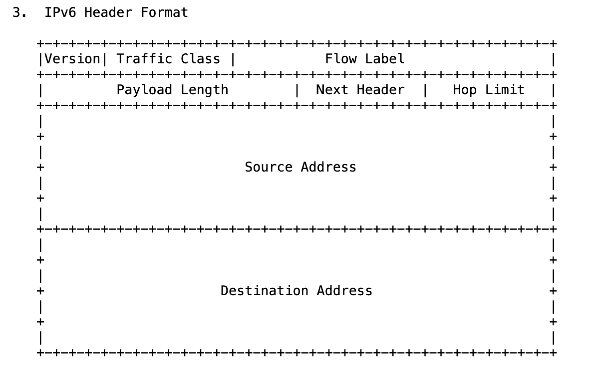
As you can see, the header format has been greatly simplified. Following are the important changes:
Fixed-sized Header (40 bytes)
IPv6 uses a fixed 40-byte header. By contrast, IPv4 headers varied between 20-60 bytes. Routers had to parse variable-length options just to find where the payload started.
Processing faster → routers can read a predictable header in one pass.
Simpler hardware → less complex parsing logic.
Future-proof → optional features were moved into extension headers instead of bloating the base header.
Removed Checksum
IPv4 recalculated a header checksum at every hop, since fields like TTL changed. This added overhead for routers. IPv6 dropped it entirely.
Integrity is already covered: the Link Layer protects frames, and the Transport Layer (TCP/UDP) checksums payload + pseudo-header.
Result: routers forward packets faster, without redundant work.
Fragmentation
In IPv4, routers could fragment oversized packets mid-flight, which caused CPU overhead and performance issues. IPv6 removes router-based fragmentation. Instead:
If a packet is too large for the next hop, the router sends back an ICMPv6 “Packet Too Big” message.
The sender is responsible for adjusting packet size. This process is called Path MTU Discovery.
IPv6 was designed in the 1990s to solve IPv4’s limitations - bigger address space, simple headers, and restoration of end-to-end connectivity. On paper, it’s the clear successor.
But in practice, IPv4 is still everywhere. Why?
NAT and CIDR stretched IPv4 much longer than anyone expected.
Transitioning the entire Internet is complex - every ISP, router, firewall, and application must support it.
Many services still default to IPv4 for compatibility.
Most modern systems run in dual stack mode (both IPv4 and IPv6 enabled). Adoption of IPv6 has been steadily growing, especially on mobile networks and in big cloud providers, but IPv4 remains deeply entrenched.
As a backend engineer, the key takeaway is:
You’ll encounter both protocols for the foreseeable future.
Be aware of IPv6, test your applications for it, but don’t be surprised if much of the real traffic you handle is still IPv4.
With that, we wrap up our deep dive into the Internet Layer. Of course, there are many other topics in this layer that we didn’t cover, or only touched briefly - things like DHCP, firewalls, ICMP, etc. This layer is vast, and people spend their entire careers working on it. You can find the referred resources here:
Previous article: But What is Networking in System Design?
Until next time, have fun and keep learning!