This post is a combination of looks at several oddities among my pile of NES and Famicom cartridges. Why, for example, do I have a copy of Gyromite when I don’t have a R.O.B.? Did I miss something interesting in my MMC blog post? And while it is the Japanese release of Kid Niki: Radical Ninja, is my Kaiketsu Yanchamaru being a little too radical? Who put the ram in the rama-lama-ding-dong? Some of these questions will be answered!
Gyromite, or if it’s on the ceiling, Gyrotite
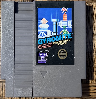
Gyromite, or in Japan, Robot Gyro, is the best game that supports the R.O.B. toy robot sold with certain models of the Nintendo Entertainment System. This isn’t really that impressive, though, considering there were only two, and the other, Stack-Up, is barely even a game.
Here’s the title screen of Gyromite. Notice something?
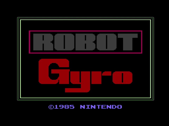
Yep, even though on paper Nintendo renamed the game from Robot Gyro (or possibly just Gyro, judging from the cartridge art), they didn’t actually make any changes in the ROM from the Japanese release. Why bother? The game doesn’t actually contain any Japanese-language text.
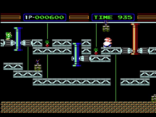
Now, you can play Gyromite without R.O.B. pretty easily, by just having someone press buttons on controller 2. In fact, pressing buttons on controller 2 is how R.O.B. works as well; but cheating in Gyromite is not the point of this blog post. The point, as many readers have probably already guessed, is what’s inside.
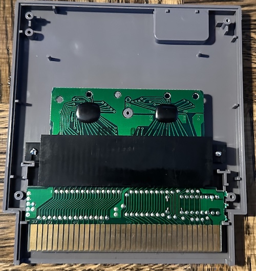
The inside of this particular copy of Gyromite is much larger than a typical NES circuit board, and is divided into two parts. Also, the top part has two epoxy blobs, shattering the claim I made that the only epoxy blob ROMs on the Famicom were from third-party developers. In fact, it’s very common to find them in early Nintendo Famicom games. I blame how hard it is to open Famicom games.
Let’s break this down further. Did I say it was divided into two parts? It’s actually three– the adaptor in the middle connecting the two of them isn’t soldered to either, it’s just a 60-pin gender changer.
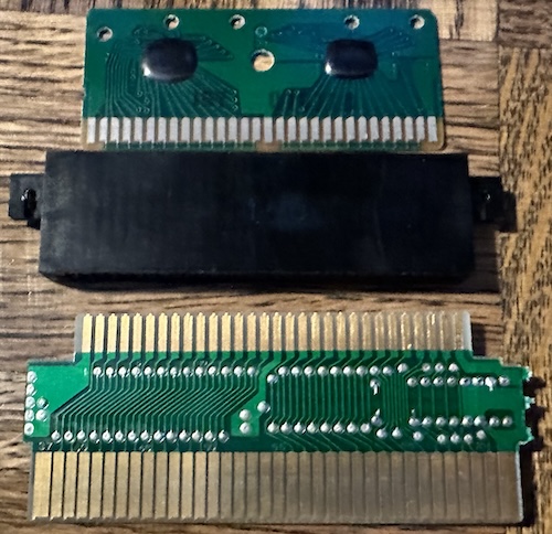
And that’s because the top PCB is a PCB you’d see in a Famicom cartridge. These cartridges shipped with an official region adapter inside. Now, today that’s not a big deal, when it’s common to mod the lockout chip away, and clone consoles with both region cartridge slots are widely available. But back in the heyday of the NES, this was the easiest way to play Famicom games without importing a whole second console. You can see that the adapter PCB has a lockout chip on-board.
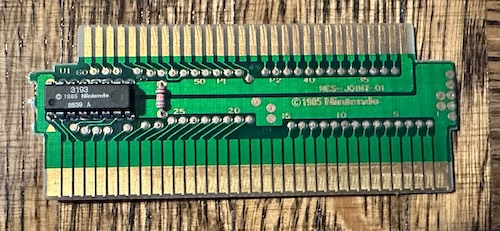
One frustrating thing here is that this adapter was never designed to be used with loose cartridges, but only PCBs. Famicom cartridges are a nightmare to open without damaging them due to reinforced plastic snap tabs, so people who wanted to use these as adapters would just take a rotary tool to it, as this blog post from 2006 shows.
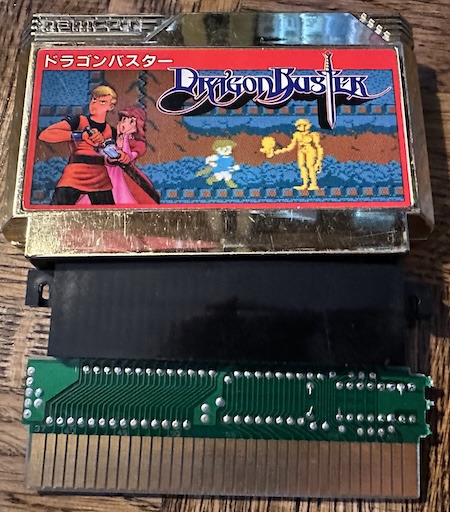
My first question about the adapter was how it handled the Famicom expansion sound. It surprised me a little bit, but maybe I shouldn’t have been surprised; at the time of Gyromite’s release, this feature of the Famicom had never been used, not even in Japan.
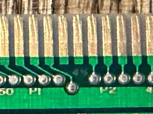
Yep, there are just two pins, the “audio in” and “audio out” pins, which aren’t connected to anything. I actually wonder if this can cause issues, if there are cartridges that expect to have something on the audio in pin and it will break their mixing circuit in a way that draws too much power or something. Obviously if the impact is limited to the audio out it won’t matter, because that’s not hooked up either.
There’s another reason this adapter ended up interesting me, but we’ll get to that after…
Intermission: Three Games in One?!
Back in the MMC blog post, I talked about the common NES pack-in title, Super Mario Bros./Duck Hunt/World Class Track Meet. This is a multicart featuring two NROM (mapperless) games, and one CNROM (discrete logic mapper), that uses MMC1, and also had some unused graphics hiding in it. There, I added this picture:
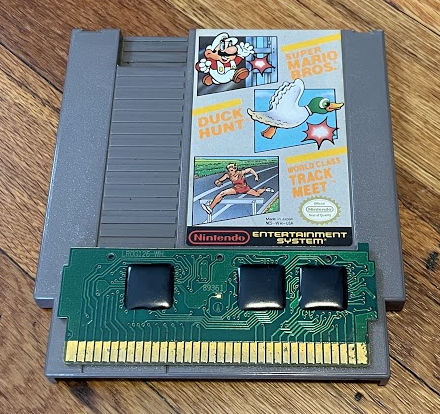
Which shows three epoxy blobs. It took ages for me to notice, but if this had been made with proper through-hole chips like most NES cartridges, there’d be four chips:
- PRG-ROM
- CHR-ROM
- Nintendo MMC1
- Lockout chip
So there being three is actually fairly interesting! Well, interesting to me. This blog is really only for me. This means that two of the chips have been combined into one of the three epoxy blobs.
In theory, the most natural two to combine feels like the MMC1 and the lockout chip. Now, Nintendo never combined a mapper with the lockout chip, even for StarTropics, a western-only release that used a unique mapper, MMC6. But Tengen did, combining their (illegal) Rabbit chip with the RAMBO-1 mapper. Notice there are only three chips on Klax, below.
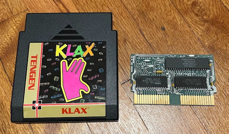
It might be useful to also include the other side of the board. And check out NESdev’s cartridge connector page. Notice the row of pads at the top; I assume this was for some sort of test harness. Also notice the transistor (?) connecting the lockout chip clock and reset signals. I don’t know what that’s for.
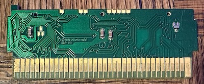
The lockout chip is the easiest to identify; it has only a few lines on the left edge of the cartridge PCB. And they all go into the central blob. The CHR-ROM is also easy to identify– the PPU data lines only need to connect to it, and they go to the leftmost blob.
The Nintendo MMC1 can control the mirroring. That means it must control the pin labeled CIRAM A10; how this pin is connected is how the two nametables will be laid out. (I explained nametable layout most recently in the AxROM blog post) And where does that go but our central blob! So we do have a combined lockout chip and MMC1. For completion-sake, we can follow some of the CPU data bus lines to find the PRG-ROM in the last remaining (rightmost) blob.
So Nintendo did combine a mapper with the lockout chip; they just did it with epoxy blobs. It’d be interesting to dissolve the epoxy somehow and see if there are two dies underneath, but I don’t think I should use the sorts of chemicals required in an apartment.
Back to the show with Kaiketsu Yanchamaru
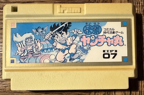
This cartridge, which has clearly seen better days and should’ve seen better dyes, is Kaiketsu Yanchamaru, the Japanese release of what was released in the west as Kid Niki: Radical Ninja. Notice by this point, Irem cartridges still had custom plastic shells, but had lost the headlight, which is a shame.
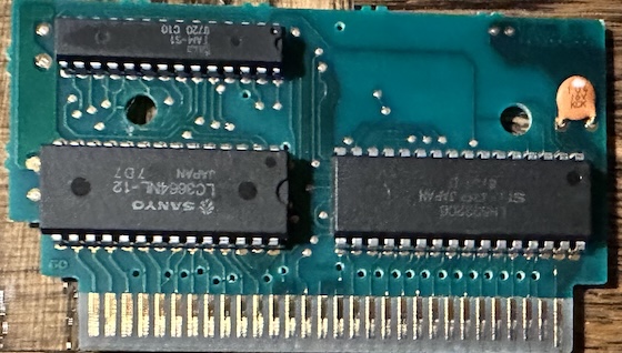
Now, while the cartridge is in rough shape, usually Famicom cartridges are pretty bulletproof, so I wasn’t too worried. After all, there just not that much to go wrong. Look at the PCB; Kaiketsu Yanchamaru uses a unique mapper chip (Kid Niki moved it to MMC1), a mask ROM, and an 8kiB static CHR-RAM. Pretty bulletproof, right?
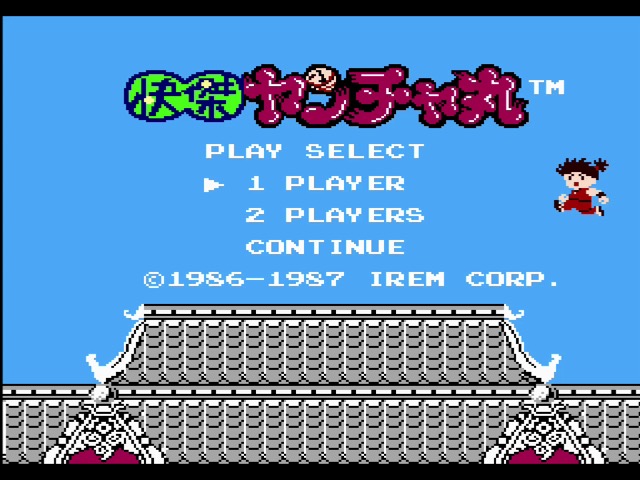
So let’s start up Kaiketsu Yanchamaru. And here’s where things get a little odd. Sure, we get the same opening as always; in English, this screen was translated as “WILL HELP YOU!”, which is the kind of enthusiasm you have to appreciate.
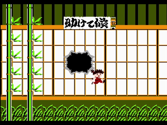
And then we get a world map, a pre world 1 message telling us who we’re going to fight… pretty typical things. But as for level 1?

It never loads. But don’t worry! Perhaps we can just choose ‘CONTINUE’ on the title screen. That’ll drop us right into the first level for sure…
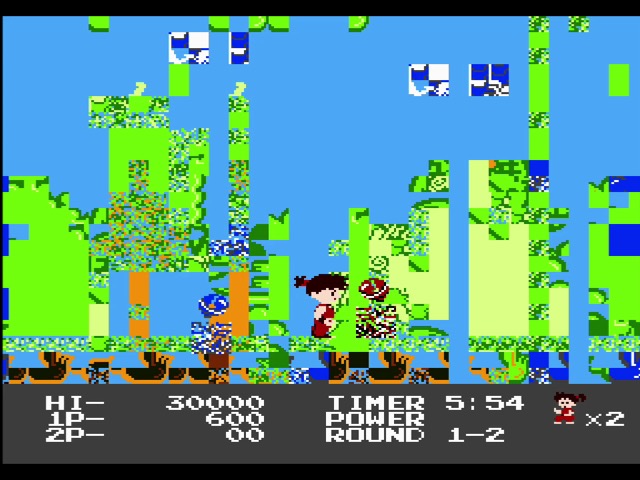
So something is going seriously wrong. It actually reminded me of problems with CHR-ROM making bad contact with the Famicom; I’ve seen that issue before, and it can result in mangled graphics. But usually it’s the wrong tile, not just garbage, and plus, Kaiketsu Yanchamaru is a CHR-RAM game. And a lot of the PRG is working fine– Yanchamaru’s sprite has loaded, as has the gameplay.
The plot thickens
And that’s where the story was when I decided to write about the Gyromite cartridge converter. As it turned out, because of these issues, Kaiketsu Yanchamaru was the only Famicom game I had handy in its PCB form to take some example screenshots. Of course, using a broken cartridge to test something is not always the best idea, but…
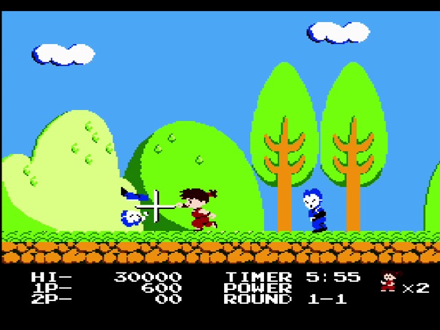
Wait, what? The game works now? Well, I’d like to say that the cartridge converter did that, but I have another theory as to why, which is a lot simpler than that. You see, all the NES screenshots in this blog post were taken off of the RetroUSB AVS, a modern FPGA clone console. It’s actually the only thing I own these days with an NES cartridge slot.
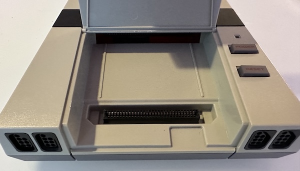
I have absolutely no need for a cartridge converter: the RetroUSB AVS has two cartridge slots, a Famicom one up straight, and the NES ones come in horizontally. It’s not quite the same as the famous “ZIF” socket on the front-loader (it’s just a normal cartridge edge connector), but I guess it’s to imitate the basic concept. So what happens if I run my copy of Kaiketsu Yanchamaru with the AVS on its side, so the cartridge is horizontal, but still using the Famicom slot?
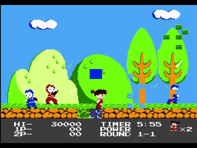
It’s glitchy still, but it’s a lot less glitchy. And notice that Yanchamaru has dropped 8 pixels when he walked into the glitchy zone. This is not a purely graphical glitch; the level data that’s been loaded is corrupted. So what does this likely mean?
Mapper 97
As noted, Kaiketsu Yanchamaru is the only game to use the mapper powered by Irem’s TAM-S1 chip, iNES Mapper code 97. This mapper is similar to UNROM; there’s a fixed bank, and a bank that the mapper controls. There are two differences:
- The mapper can also control horizontal or vertical mirroring. (This is probably why Data East chose MMC1 for the western release, as it’s the simplest Nintendo mapper with that capability)
- The fixed bank is at the top of the cartridge area (0x8000-0xBFFF), rather than the bottom (0xC000-0xFFFF). This is kind of odd and feels unnecessarily complex to me (wouldn’t you want the vectors to be fixed?) but other games like Crazy Climber did it.
In any case, let’s look at the glitches. The title screen and character graphics are loading fine. So it would seem to me that something is wrong with bankswitching; it’s able to switch in what it needs to load the title screen. Now, I don’t know the game code well enough to know what banks each of those are.
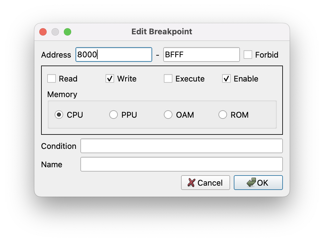
I’ll use the FCEUX emulator, and set a breakpoint for writing to the ROM area. This is how Mapper 097 (and most mappers, for that matter) change their banks. When making the title screen, the writes are 0x8E, 0x8A, 0x8C, and 0x8D. To load a level, it writes 0x8E for the level start text, which we know works, and then 0x8C, 0x80, 0x8A, 0x8D, and 0x8E. (Note that all of these banks are selected multiple times)
Now, the reason these all start with 8 is because setting the high bit is how you enable vertical mirroring (horizontal nametable layout), which is what both the title screen and the in-level mode use. 8 is 1000 in binary. So it must be the write 0x80, setting bank 0, which is causing problems, since the title screen always works.
| 0x0E | 00001110 | ✅ |
| 0x0A | 00001010 | ✅ |
| 0x0C | 00001100 | ✅ |
| 0x0D | 00001101 | ✅ |
| 0x00 | 00000000 | ❌ |
Judging by this chart at least, the questionable bit is likely bit 3 of the data bus. (remember, the data bus is numbered counting from 0) My understanding is that in CMOS logic from the time, high is often the default state and has to be pulled low, so it makes sense that it works reliably when “1” is the state.
So, long story short, here’s what I theorize based off of this data:
- Either a data line isn’t making it to the mapper, or from the mapper to the ROM, leading it to get stuck high
- This is probably due to a soldering issue, since it’s intermittent and changes based off of the orientation of the board
So resolder the PRG-ROM and the mapper and we should be good, right?
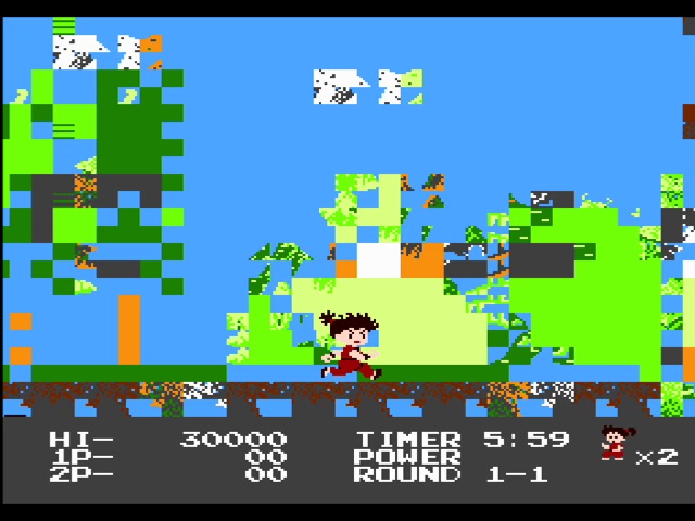
Not quite, unfortunately. But I was able to get much better results before sealing the PCB back in the cartridge, which makes me think it actually depends on cartridge flexing. I tried a few other things, like directly jumpering line D3 between the mapper and the PRG-ROM with a wire– we know it works between the PRG-ROM and the console, because the 6502 wouldn’t be able to execute code with a bad data bit.
Which is a bit frustrating of a conclusion, isn’t it? So I’ll end on a detail. You might notice that the Irem PCB is full of holes that selectively sever traces. Some are the holes that hold the PCB in, but also small drilled holes. These make it really annoying to trace out where different lines are going!
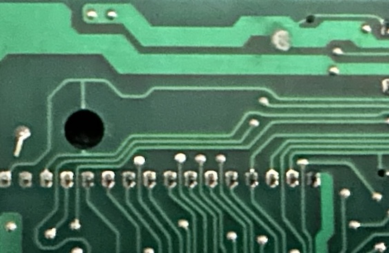
If you look on NESdev documentation for the Irem TAM-S1 chip used as the mapper for this PCB, you’ll see it actually has some functionality unused in this PCB, that could’ve been used for larger ROMs and different memory layouts. But this is the only PCB that the TAM-S1 was used in; and Kaiketsu Yanchamaru the only game.
Gyromite, on the other hand, isn’t the only game that might be found with a cartridge converter; a number of early NES titles used them, in order to bulk up the library. But only the earliest batches, and even Gyromite is often found as an NES-specific PCB. The region converter is mostly a historical oddity today, but it did provide an interesting outcome.
.png)


