.png)

- Introduction
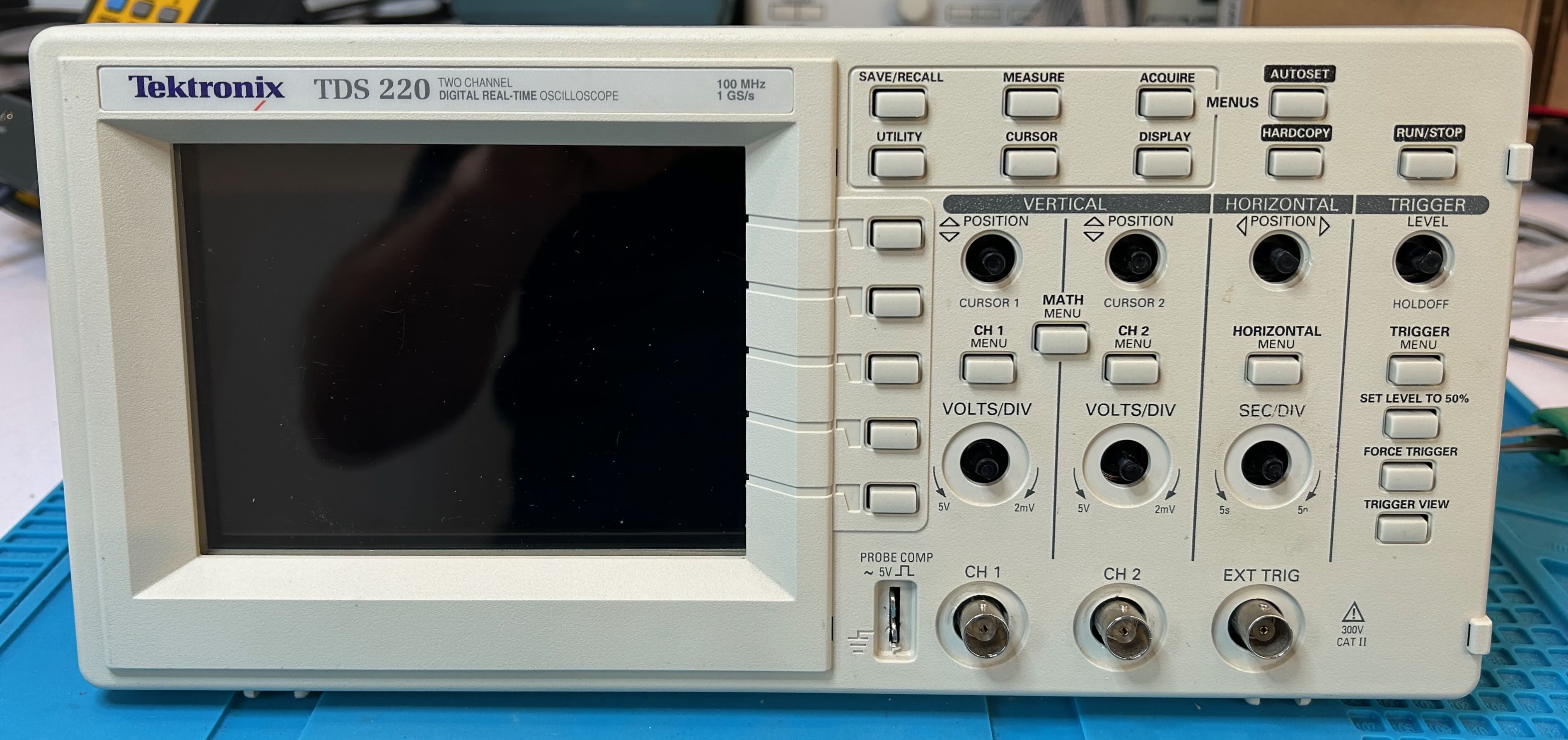
- The TDS220 Oscilloscope
- Opening Up the TDS220
- Common TDS220 issues
- Replacing the power supply capacitors
- LCD Panel Corruption
- Extracting the LCD Panel
- LCD Panel Capacitor Replacement
- LCD Panel Backlight Replacement
- Fixing the Square Wave Issue
- Conclusion
- References
- Footnotes
I found a Tektronix TDS220 oscilloscope at the Silicon Valley Electronics Flea Market. The seller told me that it worked but that the screen flickered a bit and that this model is known to have issues with leaking capacitors. He asked $25 which would be a great price for any evening of entertainment even if an oscilloscope wasn’t part of the deal, so I bought it.
Wise men claim that you should not power up an old device that with leaking capacitors, but I obviously did that anyway. The scope booted up nicely with some occasional screen corruption, as promised.
This video gives a better idea about the corruption. It’s intermittent and depends on the kind of content that is shown on the screen. It also less prevalent when the scope has warmed up. All in all, it’s not a deal breaker, the scope is perfectly usable as is, but it would nice to fix it.1
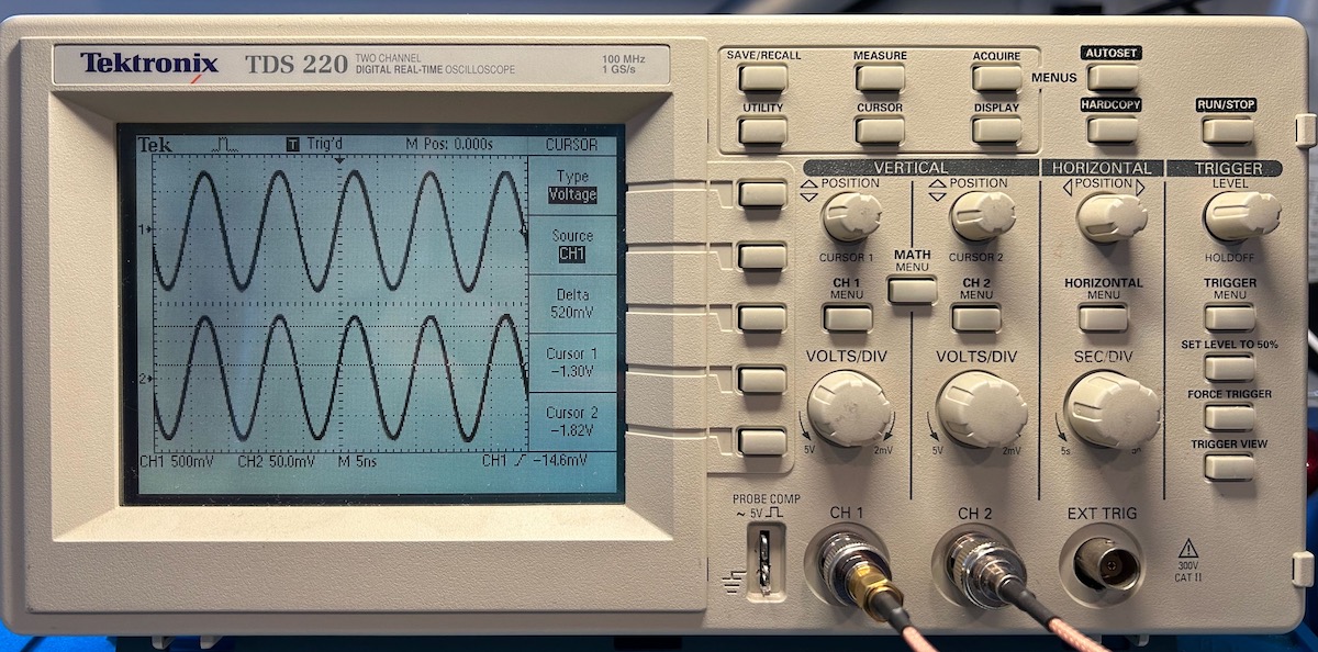
When connected to a signal generator it showed 2 sine waves:
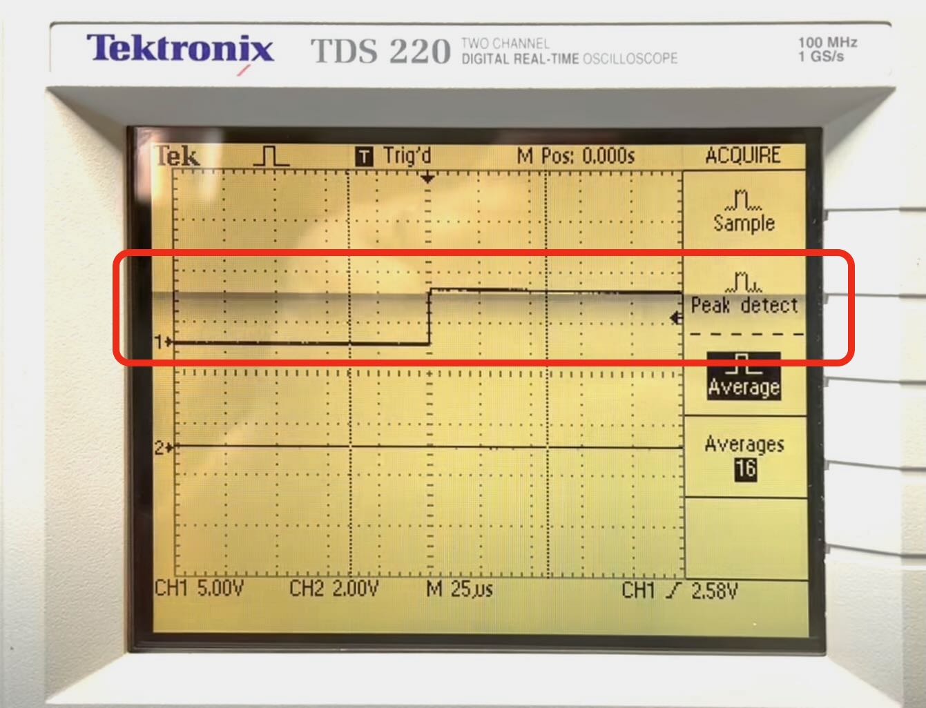
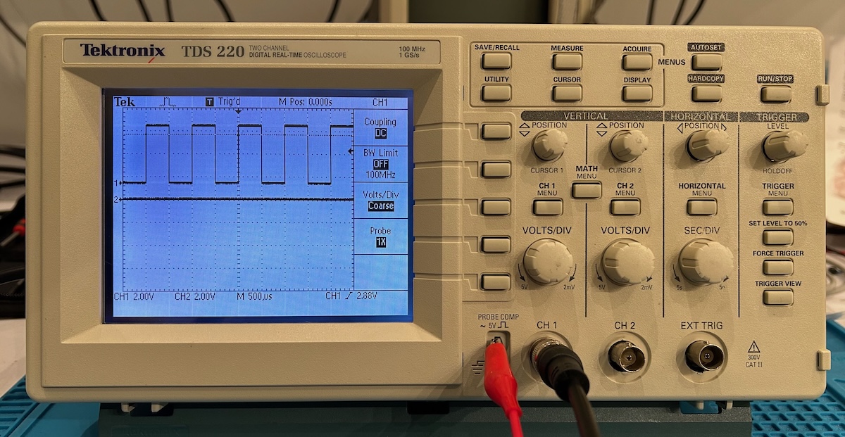
But when I connected the probe to the probe compensation pin, I got the signal below instead of a square wave:
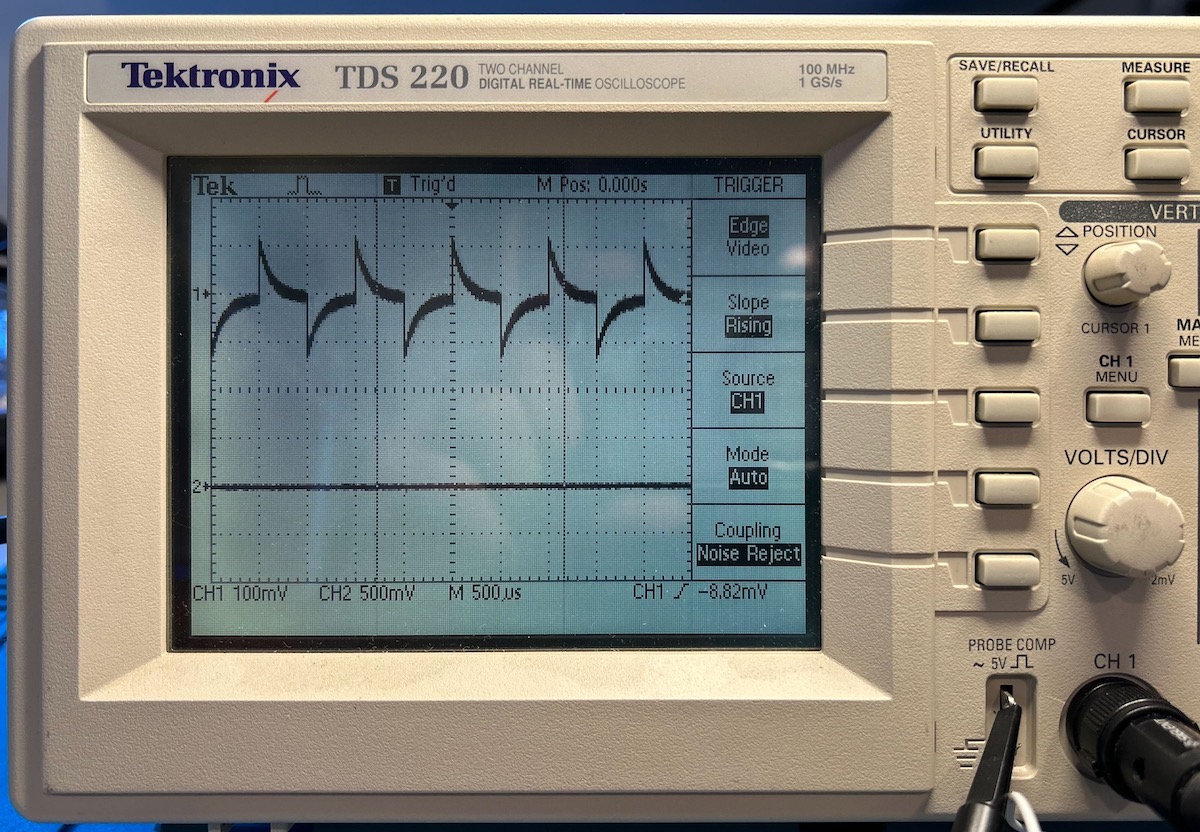
The scope had this issue for both channels.
Alright, maybe I’d get more than just an evening of fun out of it.
The TDS220 was introduced in 1997. It was a low cost oscilloscope with a limited number of features, but with a weight of just 1.5kg/3.25lb and a small size, it was great for technicians and for educational use. I’m not sure if it was Tektronix’ first oscilloscope with an LCD but, if not, it was definitely one of the early ones.
Some key characteristics:
- 2 channels
- 100 MHz/1 Gsps
- 2500 sample points per channel
- Only a few measurements: period, frequency, cycle RMS, mean and peak-to-peak voltage
With a plug-in extension board, you can add a parallel, serial and GPIB port and FFT functionality, but even with those, it’s a really bare bones scope. And yet, I expect that I’ll be using it quite a bit: it’s so portable and the footprint is so small that it’s perfect for a quick measurement on a busy workbench.
Let’s take it apart!
Opening up the TDS220 isn’t hard, but you need to do the steps in the right order and there’s a bit of bending-the-plastic involved.
Remove handle and power button
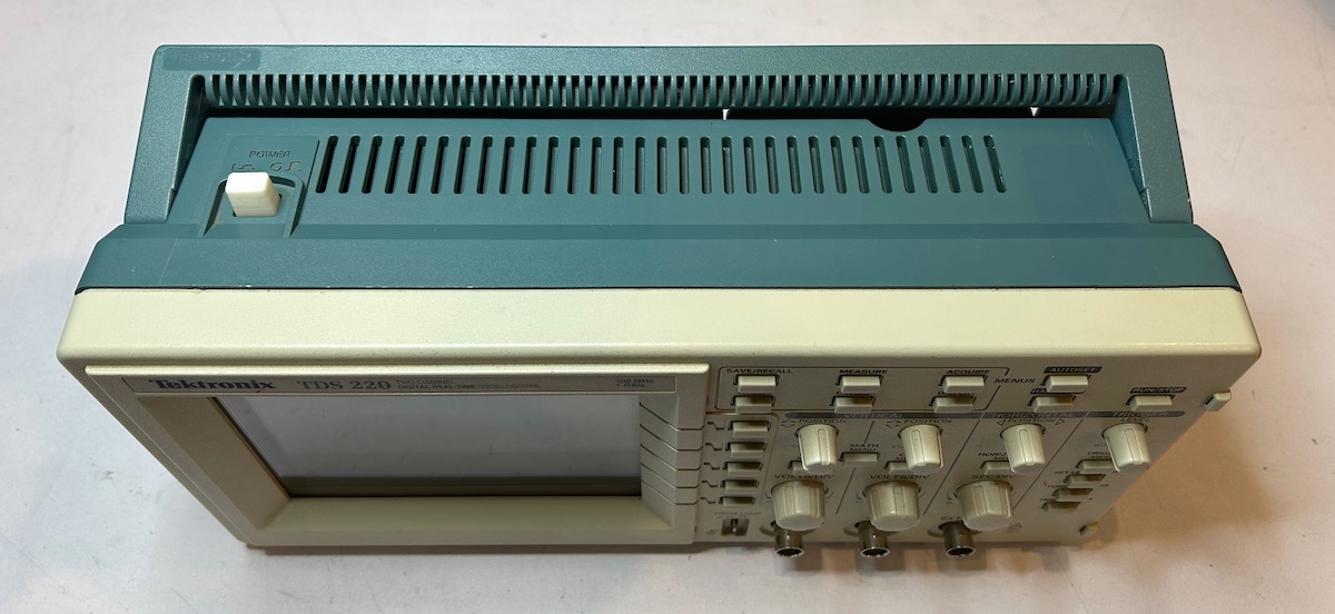
The handle must lay flat against the case to widen it and remove it. Also pull off the white knob.
Remove the 2 screws
Once the handle it removed, you get access to 2 screws, one on each side. Remove them with a Torx 15 screwdriver.
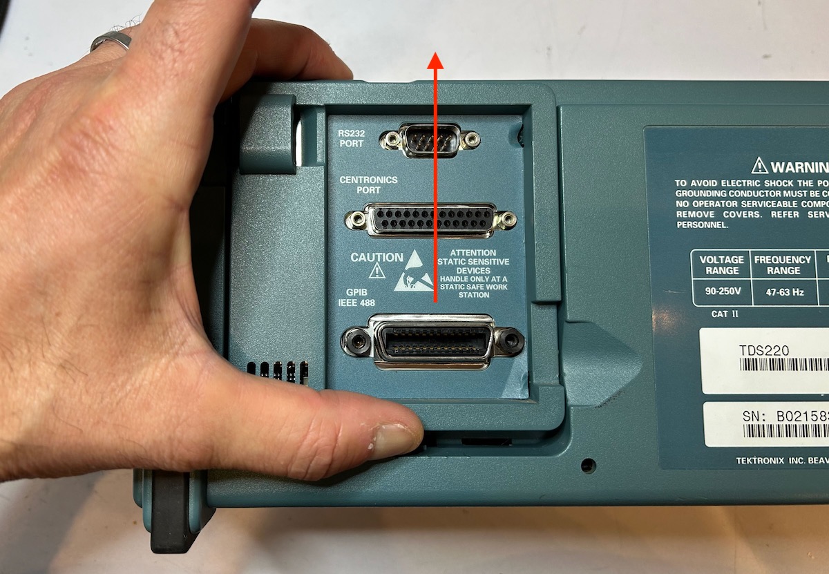
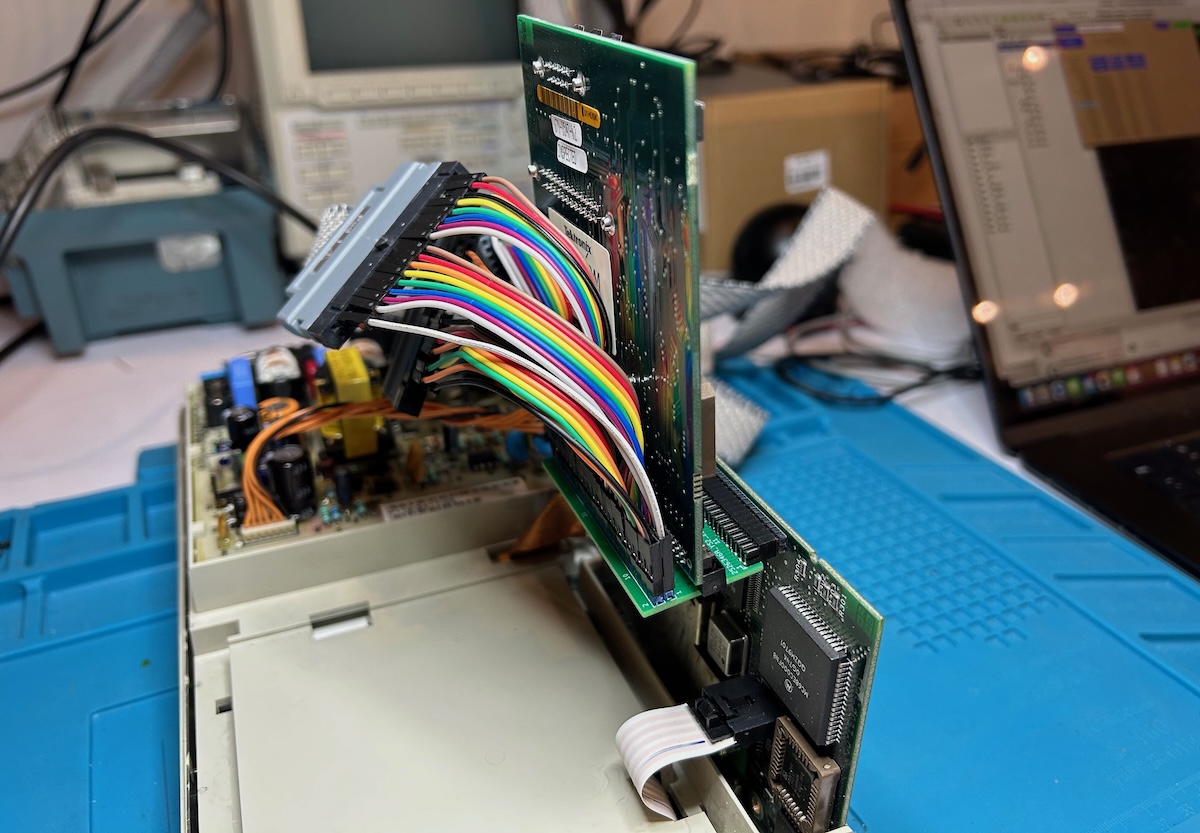
Remove expansion module
If you have a TDS2CM or TDS2MM expansion module, you need to remove it because otherwise will block the case from coming off.
It took me longer than I care to admit to figure out how to do this. There is no need to play with the tab at the top of the module, just forcefully slide the thing upwards until it disconnects from the connector at the bottom.
Pry off the back case
This is the part that I always hate, because you need to figure which location is the best to jam a screwdriver between 2 pieces of plastic. And based on the scuff marks in the picture below, others have struggled with it as well.
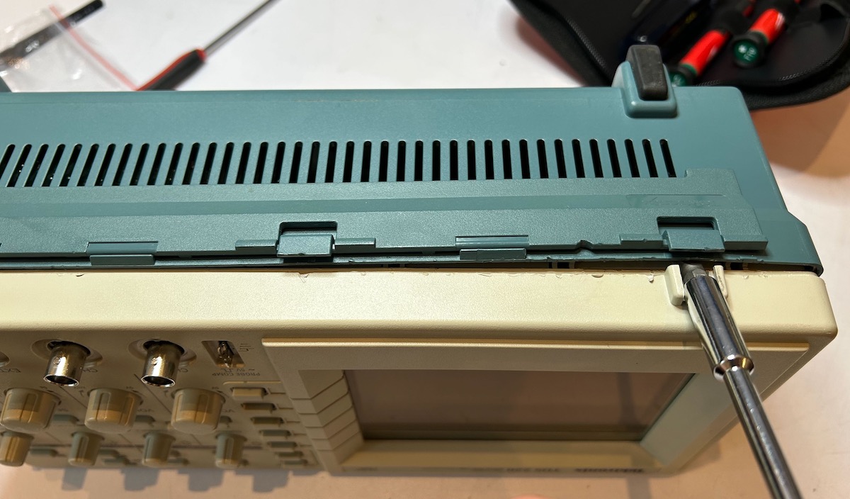
But I think I found the best way to go about it now. At the right side, insert the screwdriver horizontally between the blue and the white plastic and then lift the blue part. Insert a smaller screwdriver in the gap that you just made to prevent it from closing again and repeat the same operation in the middle and the left.
Inside exposed
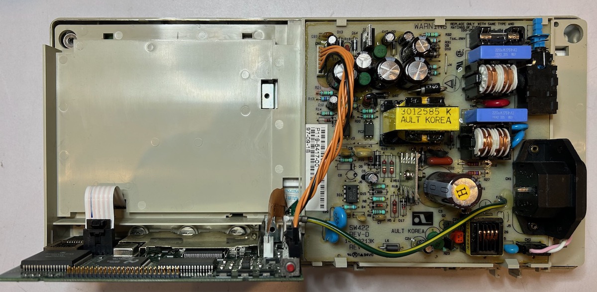
You can now take off the blue back cover and have a look at the inside of the scope.
 (Click to enlarge)
There are 2 PCBs: the left horizontal PCB contains all the acquistion and processing logic. The one on the right is the power supply.
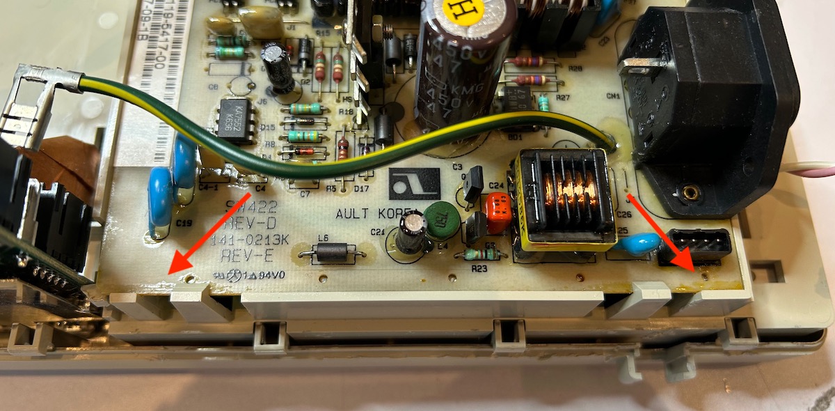
Extract the power supply PCB
To remove the power supply, unplug the orange bundle with 7 wires from the main PCB as well as the fat ground wire. The PCB is held in place by 2 plastic tabs at the bottom.
Here are the most common TDS220 issues:
- leaking capacitors in the power supply
- mechanical stress around the BNC connectors
- LCD backlight too weak or not working
-
Weak ground connection from BNC connector to power supply
Tektronix issued a product recall for this. My unit has components with dates that come after the product recall. Check out this video for a fix.
Not so common issue:
- LCD screen corruption
While I’ll document 3 of the 4 common repairs, you can find plenty of other source on the web that do the same thing. That’s not the case for the LCD screen corruption.
I didn’t take pictures of it, but the solder side of the power supply PCB was drenched in a light-brown/yellow-ish fluid. Some of that made it to the front side of the PCB as can be seen here:
 (Click to enlarge)
I’m not 100% sure about the source of this fluid because I was never able to pinpoint exactly which of the capacitors started leaking, but it’s fair to assume that this fluid was capacitor electrolyte. I decided to remove all electrolytic capacitors with new ones. There are 11 of them, listed in the table below:
I used these components for my TDS220 recapping, but there is absolutely no guarantee that these are the right ones. You need to double check everything yourself! Recapping the scope is done at your own risk!
| 1a | C3 | 47 uF | 450V | Largest on the PCB |
| 1b | C3 | 68 uF | 450V | Largest on the PCB |
| 2 | C13 | 2200 uF | 6.3V | Next to connector CN2 |
| 3 | C12 | 2200 uF | 6.3V | Next to C13 |
| 4 | C11 | 2200 uF | 6.3V | Next to C12 |
| 5 | C14 | 1000 uF | 6.3V | Next to C11 |
| 6 | C15 | 470 uF | 6.3V | Between C13 and C12 |
| 7 | C21 | 47 uF | 16V | Close to “AULT KOREA” |
| 8 | C18 | 22 uF | 35V | Next to CN2 |
| 9 | C6 | 22 uF | 35V | Next to IC1 |
| 10 | C17 | 4.7 uF | 50V | Next to C16 |
| 11 | C10 | 2.2 uF | 50 V | Next to CN2 |
Pay attention to 1a and 1b: some TDS220 power supplies have a 47 uF, other have a 68 uF capacitor. Mine had a 47 uF one. You don’t need to buy both of them.
I created this Digikey list with all these capacitors. At the time of writing this, the cost was $8.31, tax and shipping not included.
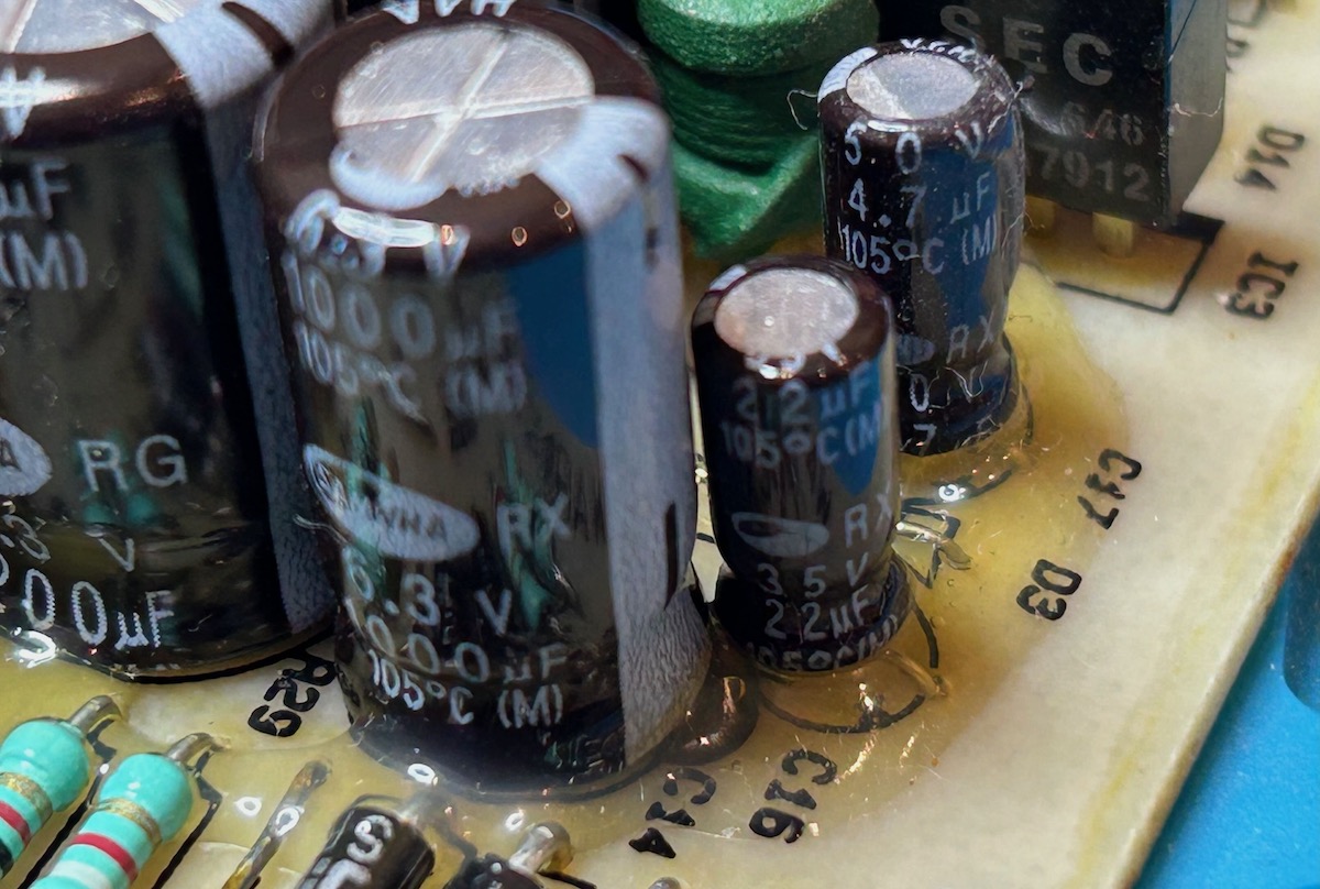
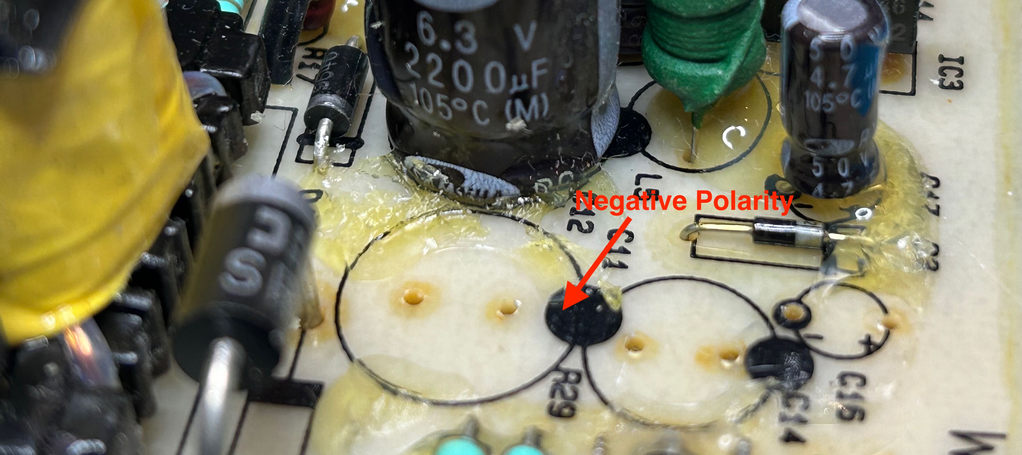
On my unit, most capacitors were fixed to the PCB with a soft, glue-like substance. Use an Exacto knife to cut it loose before desoldering a capacitor.
The PCB has markers for capacitor polarity. For smaller ones, it uses regular + and - notation. For larger ones, a black circle indicates negative polarity.
All in all, the PSU recapping process is pretty straightforward and took around 1 hour to complete.
However, after power the scope back on, the screen corruption was still there!
The LCD screen corruption is content specific and it happens for a whole pixel row at a time. I thought that it was caused by some signal corruption on the flat cable between the main PCB and the LCD panel, but this was not case. I googled around a bit, but couldn’t find any references to the issue that I was seeing, so I asked on the EEVblog Repair forum. A few hours later, I got the following reply:
Please refer to the link above, the problem that occurs is very similar to your problem
It included a link a Chinese forum that requires an account to get access to photos and any pages beyond the first one, but daisizhou helpfully posted those pictures in the EEVblog forum thread:
You need to replace some capacitors that are inside the LCD panel!
Replacing the LCD panel capacitors is not complicated, but since an LCD panel assembly is a bit fragile, you need to be careful to not destroy anything. Let’s first extract the panel from the case.
Remove the front panel knobs
The panel knobs are the main components that are still keeping the front enclosure attached to the main body. You can just pull them off.
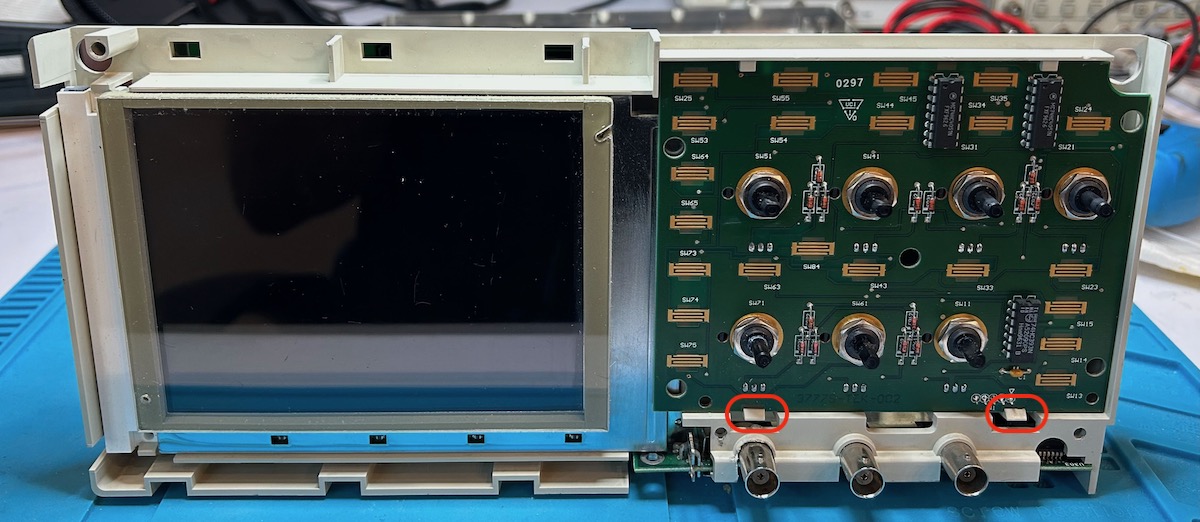
Remove buttons PCB
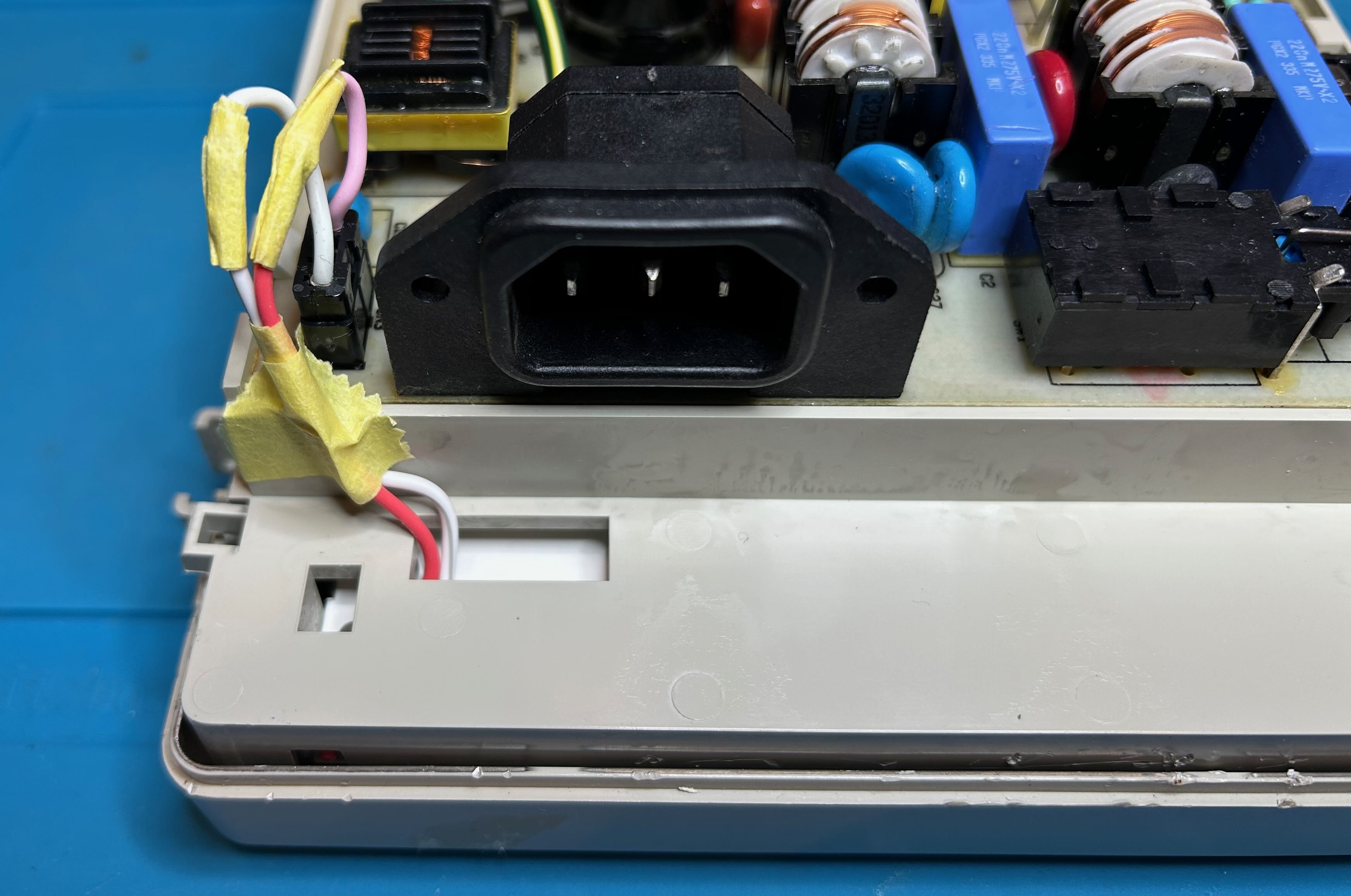
Unplug 2 flat cable connectors that links the main PCB to the buttons PCB and to the LCD panel. Not shown: also unplug the power connector of the LCD panel. It’s right next to the mains receptacle on the power PCB.
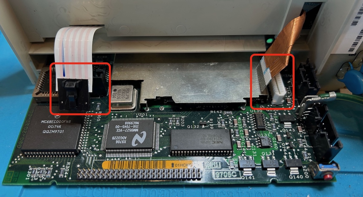
You can now remove the buttons PCB by pushing down 2 plastic tabs near the BNC connectors.
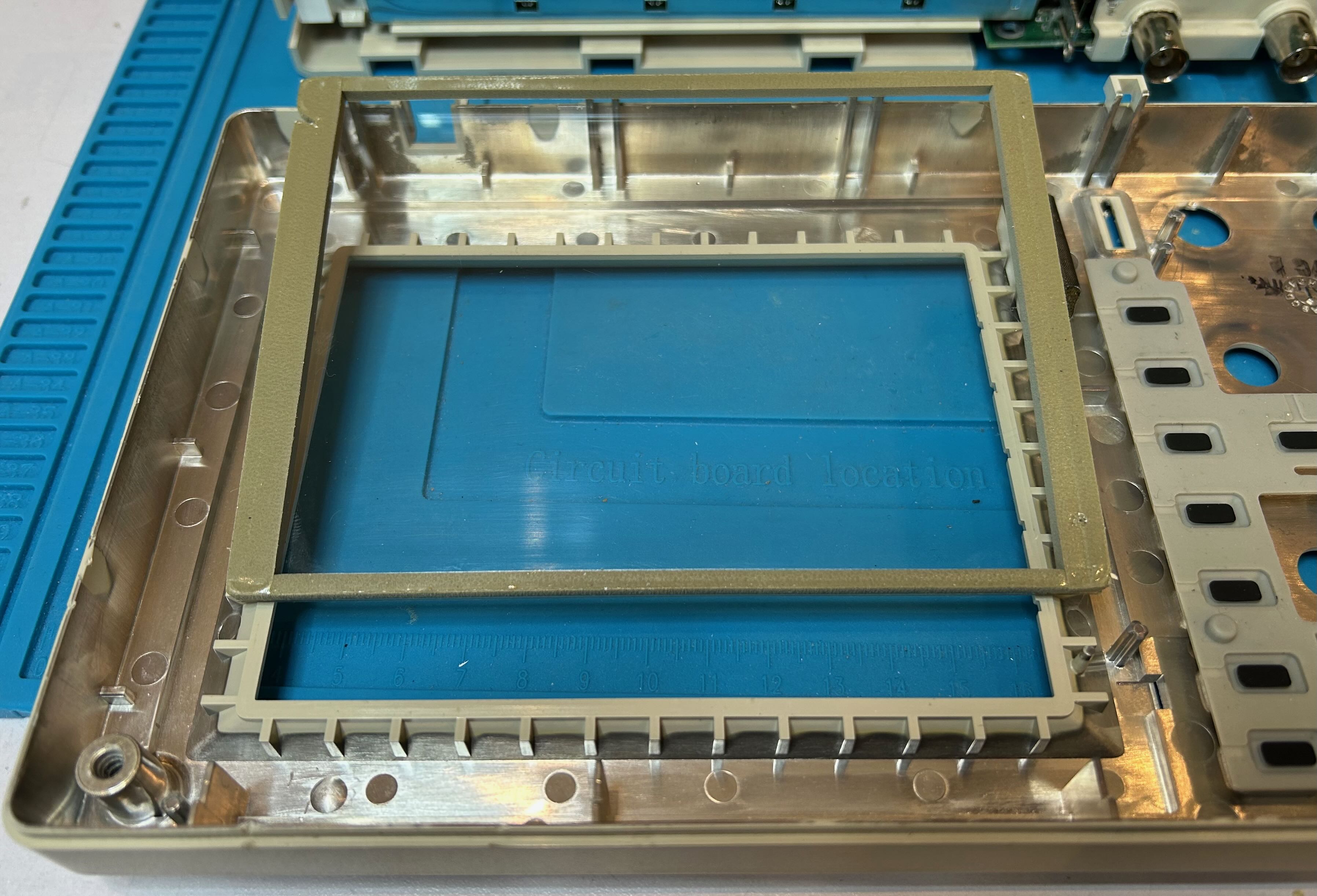
If the LCD panel was never removed before, chances are that the LCD front protector sticks to the LCD panel itself. That is the case in the picture above. The protector has a dark gray foam around a transparant piece of plastic.
Remove LCD protector
To get to the PCB inside the LCD panel, you need access to a screw that is covered by the LCD protector. A weak adhesive keeps the protector in place. You can gently pull it from the LCD screen.
There are 2 plastic tabs on the left of the LCD panel that keep it locked in place. Push those up and down to unlock the the panel. You can now lift that left size away from the main chassis and then slide the panel to the left to get the metal tab on the right out as well.
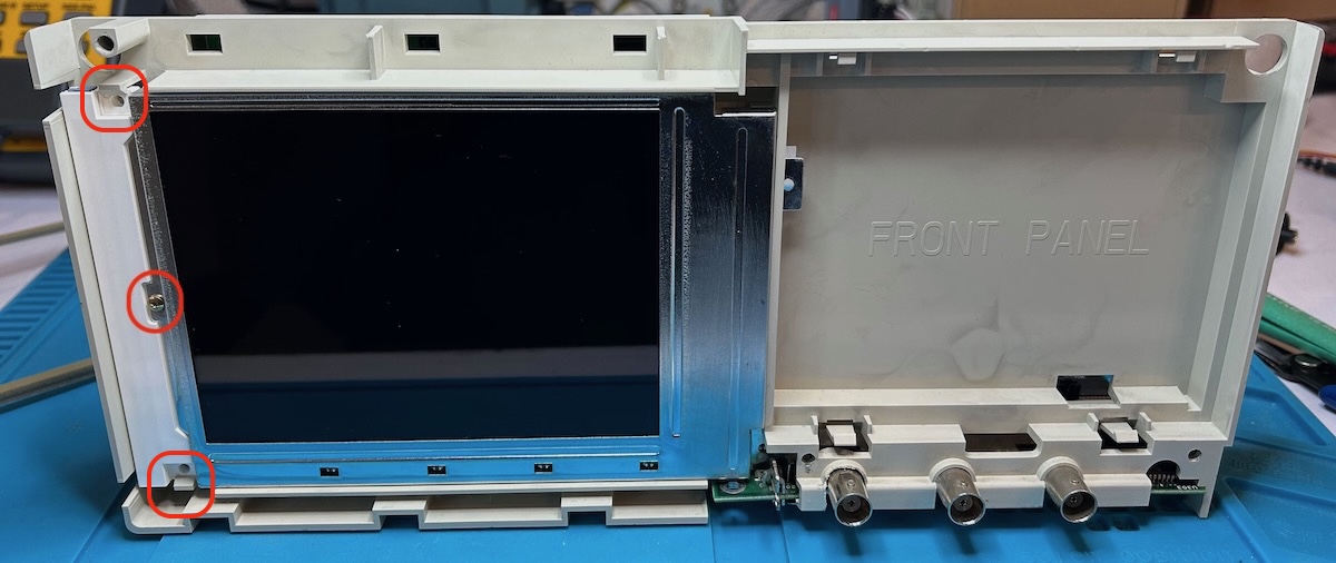
The panel is now loose. Remove the screw on the center left.
LCD frame clips
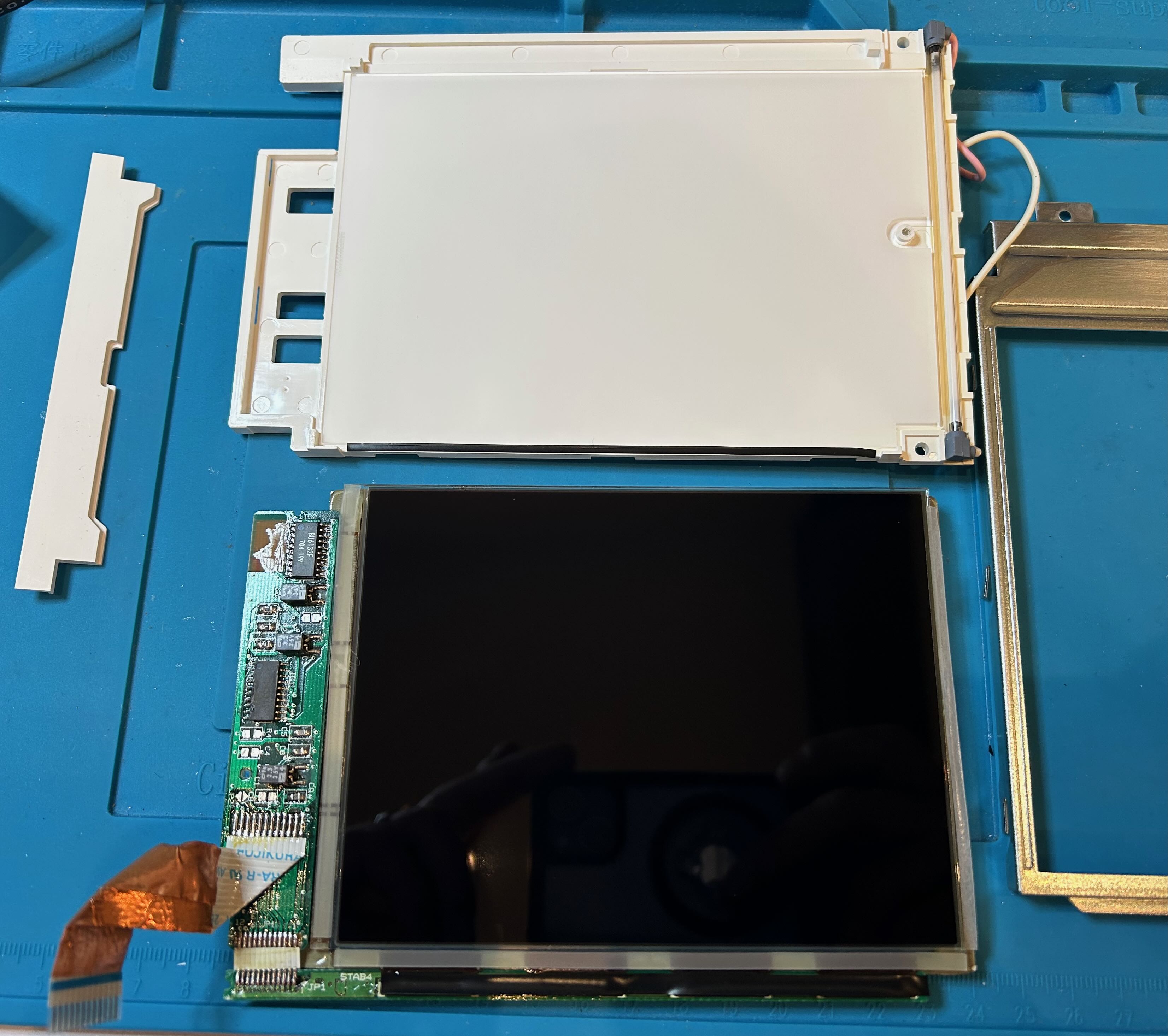
Turn the LCD panel around so that plastic back is towards you. Put something on the table to protect the LCD front screen. I used the LCD protector for that.
We can now see the 3 capacitors that need to be replaced:
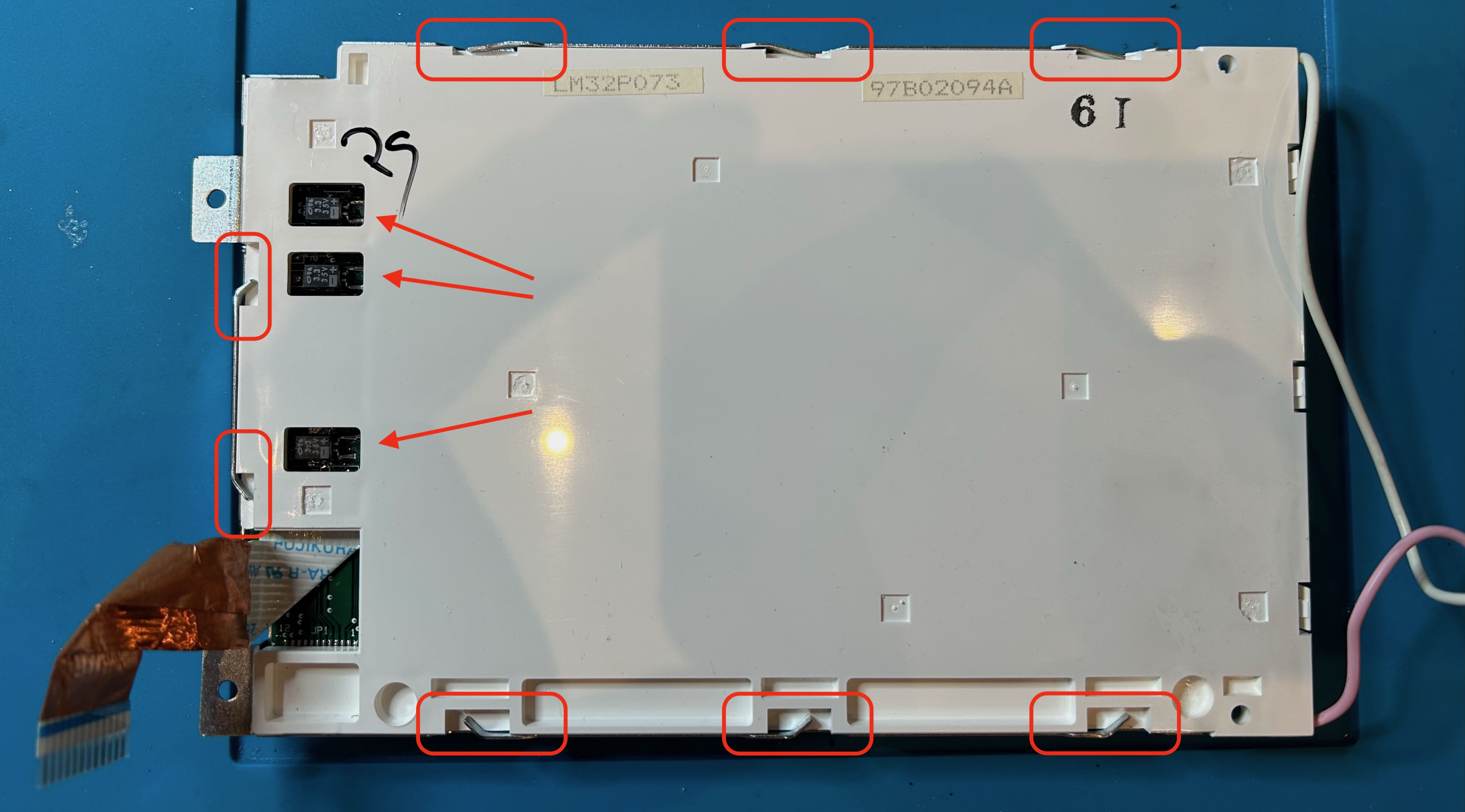
In addition to the screw from the previous step, the metal frame at the front of the LCD panel is held in place by 8 metal tabs the bend into gaps of the plastic back. Use nose pliers to straighten those tabs.
You can now remove the plastic back. Finally, you have access to the LCD PCB!
Here are the 3 capacitors in close-up. They’re 3.3 uF 35V polarized capacitors.
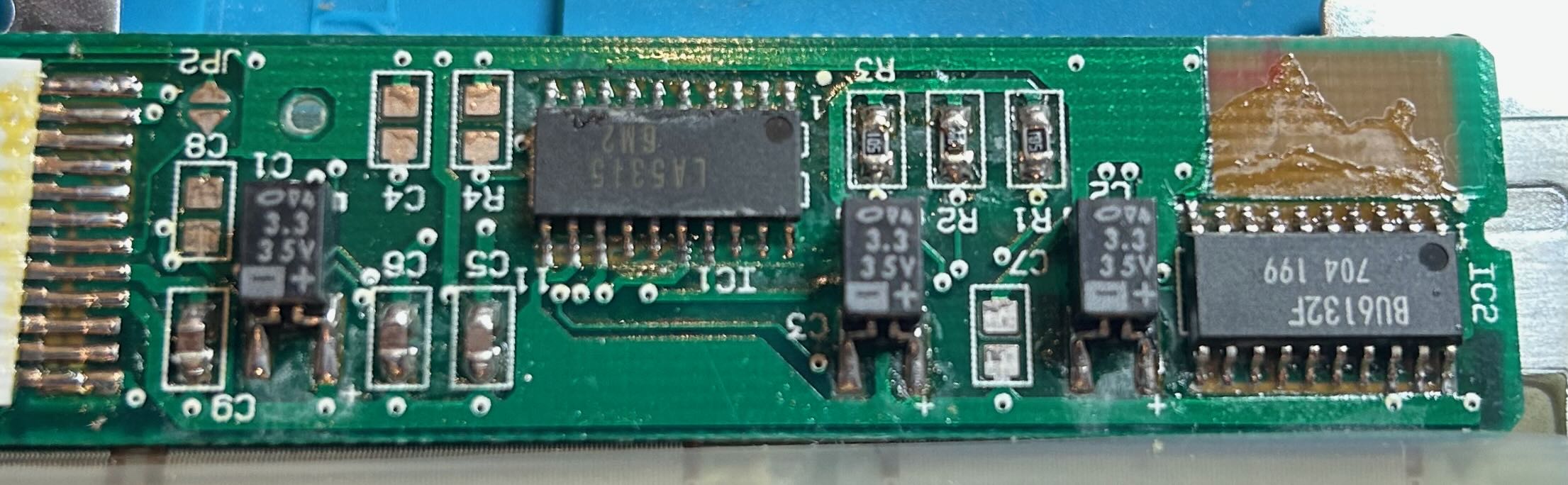
However, they are not your garden variety SMD tantalum capacitors! Notice how both leads are on the same side of the capacitor. When we look at the other side, we can see how the capacitor has a cylindrical core with a box plastic enclosure around it.
I couldn’t find any exact replacement. On that Chinese forum, they used regular electrolytic caps instead, so that’s what I did as well.
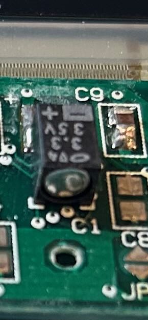
The plastic back has cut-outs for the 3 capacitors. On the Chinese forum, they made those cut-outs a bit larger to make the new capacitors fit, but that was not necessary in my case: the holes were large enough as-is, as long as you took care to solder them as close to the inside of the PCB as possible.
You can see this here:
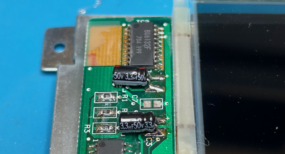
The top capacitor is soldered too far to the left, the bottom one is fine. I had to resolder the top capacitor one to make it fit in the cut-out.
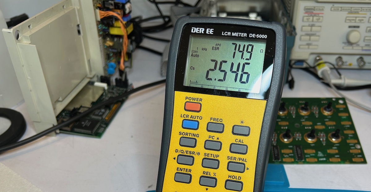
One of the old LCD capacitors came in at 2.5 uF and a 75 Ohm ESR. The replacement ones have an ESR of 6 Ohm…
With the capacitors replace, you can now put the LCD panel back together in reverse order. But don’t mount it back into the chasses just yet!
The LCD panel uses a small CCFL tube as backlight. Over time, these CCFLs lose their intensity which makes the screen less bright.
You access the CCFL tube by removing an easy to remove cover on the left of the panel:
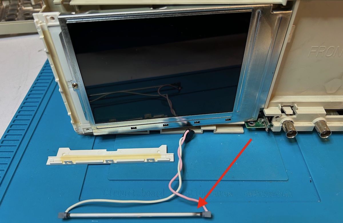
Notice how some parts of the tube are black.
Replacement tubes can be found on eBay. Sellers vary, but just search for “CCFL lamp tds220” and you’ll find what you need. Prices have gone up due to tariffs, I paid $17.46 including shipping.
The new lamp doesn’t come with the right connector, so some soldering is required to transfer the connector from the old lamp to the new one. I first placed new tube in the LCD panel and the LCD panel in the chassis before soldering the connector. That made it easier to get the length of the wires correct.
After the replacement, the screen brightness was noticable… dimmer, but that’s normal: new CCFL lamps needs a few minutes to reach their full brightness.
You can find plenty of videos on Youtube of this backlight swap and authors always claim to see a significant improvement. I’m not so sure for my case: it’s not dimmer, but I can’t honestly say that it’s much brighter. In one case, someone replaced the CCFL lamp with an LED PCB. I looked around for suitable LED PCBs to do that as well but didn’t find anything that worked. If you want to try that, understand that the voltage of the CCFL lamp is much higher than the 5V or so you’d need for LEDs!
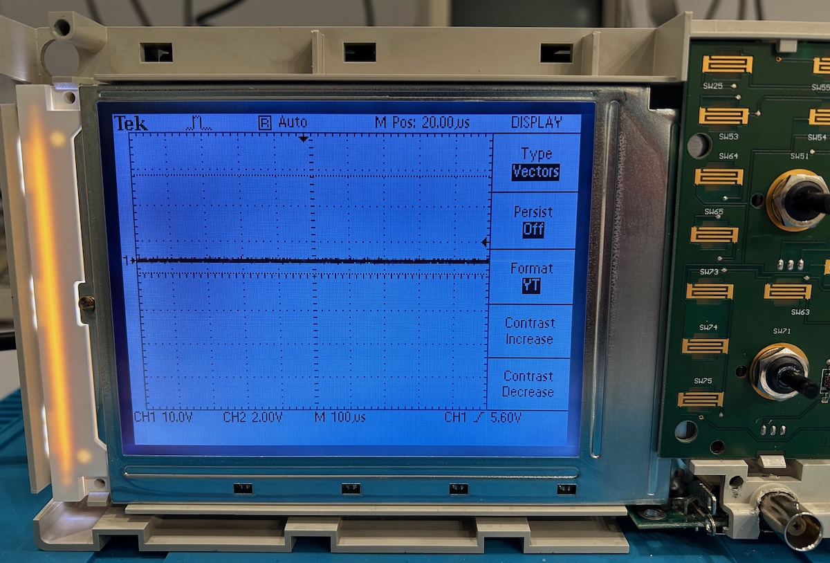
The corrupted signal compensation square wave issue was solved by reheating the solder of the BNC connector pins on the main PCB.
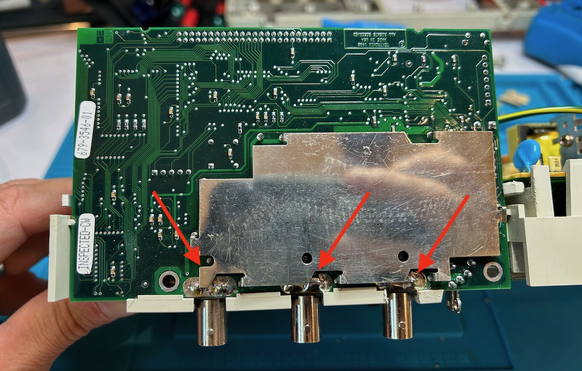
To do this right, you need to remove the RF shielding at the bottom of the main PCB, but I just squeezed my soldering iron into an open space and hope for the best. It worked:
The TDS220 is working perfect fine again. It measures signals correctly, there is no LCD screen corruption, and the brightness is fine. It’s still sitting on the bench, connected to a logic analyzer, but that’s still a work in progress and may be a topic for a future blog post.
- Tony Albus - Tektronix TDS220 Backlight Replace and Restore
- Max’s Garage - Repairing Two Digital Oscilloscopes from the 90s! Tektronix TDS210 and TDS220 Restoration
- Tektronix TDS200 CCFL to LED backlight replacement
- EEVblog forum - Recap list
- EEVblog forum - TDS 2002B repair
- NFM - Tektronix TDS210 TDS220 Oscilloscope Recall and Loose BNC Fix

