.png)

I recently found myself needing to change the monitor that a cheap HDMI “dummy plug” pretended to be. It was a random one I had bought on Amazon several years ago that acted as a 4K monitor, and I needed it to be something simpler that didn’t support a 4K resolution. The story behind why is a long one that I’m still figuring out and might eventually become a separate blog post in the future.
If you’re not familiar with dummy plugs, here’s a quick primer: they are tiny dongles you can plug into an HDMI, DVI, etc. port that don’t actually do anything with the video signal. They simply have the minimum circuitry needed for a video source device, like a computer, to think that a monitor is hooked up. In general this entails a pull-up resistor on pin 19 (HPD) to +5V, as well as a little I2C EEPROM chip containing the Extended Display Identification Data (EDID). This is useful for headless machines to force the OS to think a monitor is attached.

The EDID contains all the info about the monitor: the manufacturer, manufacture date, supported resolutions, audio channels, color space, and stuff like that. My goal was to replace the dummy plug’s EDID with an identical copy of an EDID from one of my many 1080p HDMI capture devices. Then, the computer I plugged it into would think the capture device was plugged in instead of a 4K monitor, and everything would be hunky dory.
I wasn’t sure if the dummy plug’s EDID EEPROM would be programmable, but I decided to give it a shot. There was a chance that it would have its write-protect pin configured to disable programming, but I figured it wouldn’t hurt to try.
Conveniently, I found that my Raspberry Pi Zero has an I2C controller wired to the correct pins on its HDMI port. This makes sense — the Pi would need to be able to read the EDID of an attached monitor. This post on the Raspberry Pi Forums and this GitHub comment were helpful for explaining which I2C controller(s) to look at in software on various Pi devices:
- Pi 0-3:
- /dev/i2c-2
- Pi 4:
- /dev/i2c-20
- /dev/i2c-21
- Pi 5:
- /dev/i2c-11
- /dev/i2c-12
Before I go further, I want to make it clear that it may be possible to screw up a monitor if you follow these instructions while a real monitor is plugged in and it doesn’t have its EDID protected. Be careful to only run these commands if you have something attached to the HDMI port that you’re not afraid of bricking, such as a dummy plug! Also, make sure you are confident you’re on the correct I2C bus! Always read the EDID and parse it first to make sure it actually contains an EDID before you attempt a write. If you attempt these commands on a PC, it’s possible that you could accidentally flash hardware that isn’t an EDID, like a RAM module’s SPD EEPROM.
Starting from a fresh Raspberry Pi OS Lite install, I performed the following modifications:
- sudo raspi-config
- Under Interface Options, enable I2C as described in the Raspberry Pi documentation.
- sudo apt install i2c-tools
- Unfortunately, this requires network access, which creates a bit of a problem if you are on a Pi Zero. You might need a USB-Ethernet adapter to make this happen. Another slightly crazy option is to temporarily take the SD card out of your Pi, put it into your desktop PC running Debian/Ubuntu, run sudo apt install binfmt-support qemu-user-static on your PC, chroot into the SD card’s rootfs (options 1.3 and 2.1 worked for me), and run the apt install command inside of the chroot.
And with those prerequisites out of the way, I was ready to start tinkering with the dummy plug’s EEPROM. Note that I also needed an HDMI-to-Mini-HDMI adapter.

Since I was using a Raspberry Pi Zero, I chose bus 2. You could change the number below to something else on a different model, as listed above (e.g. 20 or 21 on a Pi 4).
I ran i2cdetect to see if the EDID EEPROM was recognized:
This came back with the following result, showing that an I2C device was detected at address 0x50, which is exactly the address used for EDID:
0 1 2 3 4 5 6 7 8 9 a b c d e f00: -- -- -- -- -- -- -- --
10: -- -- -- -- -- -- -- -- -- -- -- -- -- -- -- --
20: -- -- -- -- -- -- -- -- -- -- -- -- -- -- -- --
30: -- -- -- -- -- -- -- -- -- -- -- -- -- -- -- --
40: -- -- -- -- -- -- -- -- -- -- -- -- -- -- -- --
50: 50 51 52 53 54 55 56 57 -- -- -- -- -- -- -- --
60: -- -- -- -- -- -- -- -- -- -- -- -- -- -- -- --
70: -- -- -- -- -- -- -- --
Interestingly, this particular dummy plug also responds with addresses 0x51 through 0x57 present. These other addresses seem to contain copies of the same EDID. Not all dummy plugs show up like this — another one I have only detects 0x50. Anyway, next, I dumped the original EDID from it:
This is read-edid version 3.0.2. Prepare for some fun.
Attempting to use i2c interface
Only trying 2 as per your request.
256-byte EDID successfully retrieved from i2c bus 2
Looks like i2c was successful. Have a good day.
Nice! To make sure I got a good dump, I tried it twice and compared the results to make sure they were identical. Then I printed it in a format suitable for copying/pasting to something like edidreader.com:
This spit out a nice little hex dump of the EDID that was stored on it:
00 ff ff ff ff ff ff 00 1a ae 31 9d 00 00 00 0001 19 01 04 85 58 31 78 3e a4 fd ab 4e 42 a6 26
0d 47 4a 2f cf 00 e1 c0 d1 c0 b3 00 a9 40 95 00
81 80 81 40 81 c0 02 3a 80 18 71 38 2d 40 58 2c
45 00 e0 0e 11 00 00 1e 4d d0 00 a0 f0 70 3e 80
30 20 35 00 c0 1c 32 00 00 1a 00 00 00 fc 00 48
44 4d 49 20 4d 6f 6e 69 74 6f 72 0a 00 00 00 10
00 00 00 00 00 00 00 00 00 00 00 00 00 00 01 4a
02 03 46 70 52 e1 60 5f 5d e6 65 64 62 10 04 03
1f 20 21 22 13 12 01 26 09 7f 07 11 7f 50 83 01
00 00 6e b9 14 00 40 00 18 78 20 00 60 01 02 03
04 67 d8 5d c4 01 78 00 07 6c 03 0c 00 20 00 f0
78 20 00 40 01 04 08 e8 00 30 f2 70 5a 80 b0 58
8a 10 c0 1c 32 00 00 1e b7 e6 ff 18 f1 70 5a 80
58 2c 8a 00 ff 1c 32 00 00 1e 56 5e 00 a0 a0 a0
29 50 30 20 35 00 80 68 21 00 00 1a 00 00 00 e9
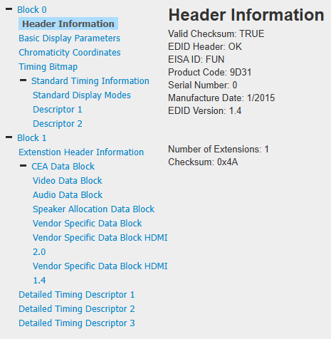
Pasting it into the site linked above, I could see it was a valid EDID:
Now that I was confident I had the dummy plug’s original EDID backed up, I unplugged it from the Pi’s HDMI port and plugged my capture device in instead, and repeated the exact same procedure to dump its EDID:
I confirmed it was also a valid EDID. Finally, I unplugged the capture device and connected the dummy plug again, and wrote the capture device’s EDID to it with this fun little code snippet. There are tools out there that can probably do this more efficiently, but hey, this works and doesn’t require any special packages other than the standard userspace Linux I2C tools and bash or dash!
As a quick explanation, this reads the entire EDID (probably 256 bytes in size) from the dump file created earlier, and formats it into an array of two-digit hex strings using od. Each entry in the array represents one byte in the EDID. Then it loops over each byte, prepending a “0x” prefix and writing it out to the EEPROM using i2cset.
After running this code, I re-read the EDID from the dummy plug and checked to see if it matched the file I started from:
The diff command produced no output at all, which indicated that the new dump was identical. The dummy plug’s EEPROM had successfully been reprogrammed with the EDID from my capture device!
Of course, at this point I anxiously plugged it into my test computer, powered the computer up, and noticed that everything was great and it acted as though my HDMI capture device was plugged in instead of a 4K monitor. Success!
I thought I’d share this procedure in case it’s useful for someone else in the future. You could probably also use this solution to go in the opposite direction — upgrading an old 1080p dummy plug to add 4K support. Again, be careful with these commands! I wouldn’t recommend tinkering with I2C writes on an actual PC. Use a Raspberry Pi so you don’t accidentally brick your desktop PC.


