.png)

I recently experimented with embedded C for AVR with Bazel and it was a great experience using regular, plain GCC for AVR to build embedded C code and deploy it on an open-source simulator (please check that guide for pointers on how to set up the latest AVR development environment on your machine). That only ended with a simulation, though, and this time I’m looking at deploying the code on a real, physical microcontroller. Additionally, I don’t want to use any development boards and instead just want to prototype with the bare microcontroller.
The focus of this text is not so much on the application code, but rather on the end-to-end experience of building and deploying something while avoiding proprietary software, staying in control of the build flow, and finally deploying on the target without downloading annoying proprietary software or buying expensive accessories.
Note: Because, per above, the focus is not on the application code and its quality, I simply generated the application code itself using AI. The only verification done is “it runs on my machine” (or should I say microcontroller), so please do not trust the code itself too much.
Table of contents
Open Table of contents- GitHub repo
- The experiment setup
- C code
- Compiling
- Flashing the microcontroller
- Running the system
- Conclusion
GitHub repo
The final code for this experiment is on GitHub here. We’ll be referencing the code from it as we go.
GitHub should be the source of truth and may be slightly out of sync with the code below.
The experiment setup
The goal is to have the microcontroller drive the intensity of a standard 4-pin PC cooler fan using some simple logic. More specifically, we want the microcontroller to cycle through low intensity, then mid intensity, and finally high intensity, before switching back to low intensity and repeating.
Initially, I considered using a spare 3-pin cooler and thought I could achieve different intensity levels by driving a transistor using PWM or something like that. However, I learned that 4-pin coolers give you a dedicated pin for PWM for this exact purpose, so I simplified my setup to just use that kind of cooler, though I had to order a new one from Amazon.
Therefore, the setup is simple:
- Write an AVR program to cycle PWM parameters on a single pin.
- Compile it using mainline GCC.
- Flash it onto a microcontroller.
- Run!
The microcontroller specifically used for this experiment is the DIP-28 flavor of ATmega328p. Per the article title, it should be available for around $2. Depending on the store and current prices, it could of course be slightly higher or lower.
C code
As mentioned before, I just asked AI to write the code out for me. I was too lazy to read any PDFs. Therefore, there may be a better solution to do this, and some values could probably be more accurate, but this should do for a quick experiment.
Specifically, I didn’t quite understand what the magic 249 constant suggested by AI is for… but it worked! Again, the focus here is more on tooling rather than developing the code. The main function itself should be self-explanatory, and it’s where all the business logic lives.
/* * ATmega328P Fan PWM Controller * * Controls a 4-pin PC fan using PWM on the blue wire * Automatically cycles between low/medium/high speeds every 3 seconds */ #include <avr/io.h> #include <util/delay.h> #define F_CPU 1000000UL // 1 MHz clock frequency // PWM values for different speed settings #define PWM_LOW 82 // ~33% duty cycle (82/249) #define PWM_MEDIUM 165 // ~66% duty cycle (165/249) #define PWM_HIGH 249 // 100% duty cycle (249/249) void PWM_init(void) { // Set Timer1 for Fast PWM mode with ICR1 as TOP // This allows us to set custom frequency TCCR1A = (1 << COM1A1) | (1 << WGM11); // Non-inverting mode, Fast PWM TCCR1B = (1 << WGM13) | (1 << WGM12) | (1 << CS10); // Fast PWM, no prescaler // Top value for 25kHz PWM frequency // We'll use 249 for easier percentage calculations ICR1 = 249; // Set initial duty cycle to 0 (fan off) OCR1A = 0; // Set the output pin DDRB |= (1 << PB1); } void set_fan_speed(uint16_t pwm_value) { OCR1A = pwm_value; } int main(void) { PWM_init(); while (1) { set_fan_speed(PWM_LOW); _delay_ms(3000); set_fan_speed(PWM_MEDIUM); _delay_ms(3000); set_fan_speed(PWM_HIGH); _delay_ms(3000); } return 0; }Compiling
The fact that AVRs are well supported by mainline GCC is amazing. As we’ve seen before, that means we can easily integrate this build flow into a higher-level build system like Bazel, or anything else that expects GCC.
Furthermore, targeting the specific chip was as easy as passing a single flag value.
Therefore, to build the code, I used:
avr-gcc -Os -g -mmcu=atmega328p -DF_CPU=1000000UL -o program.elf program.cThe only unintuitive bit here is the F_CPU symbol. This is because some logic used under the hood needs to know exactly how long each clock cycle takes. For example, if we want to make the core busy-wait for 500 ms, the delay logic needs to know how many iterations of busy-waiting to do based on the core frequency. Since we’re going super hacky here, we won’t connect an external oscillator, so we’ll only use the internal 1 MHz clock. That’s exactly the frequency symbol value passed here.
This produces the ELF file, which can then be used to derive the HEX binary that can be directly flashed onto the microcontroller. To derive the HEX file, I used:
avr-objcopy -O ihex -R .eeprom program.elf program.hexFlashing the microcontroller
There are multiple ways to load the program bytes into the microcontroller. However, it seems that for all these solutions, the usage of the avrdude tool is one common theme.
More specifically, avrdude can take a HEX file as input and use one of its backends to transfer those bytes into the microcontroller memory. A backend is chosen based on how you’re physically connecting the microcontroller for programming.
In my case, I opted for SPI flashing. In theory, this means that any device that works over the SPI protocol can send the right messages to the target microcontroller and flash it. In fact, a couple of interesting backends I’d like to highlight exist for avrdude:
- Arduino: From what I understand, if you have a spare Arduino, you can use it as an AVR programmer. Your desktop can upload bytes to it while the Arduino takes care of the SPI flashing protocol.
- Raspberry Pi: RPi has an SPI port directly exposed, which is natively recognized by Linux. avrdude can be built to offer a linuxspi backend for flashing directly via SPI, but it remains unclear if this is a patch provided by someone or part of mainline avrdude. Regardless, it’s very much possible.
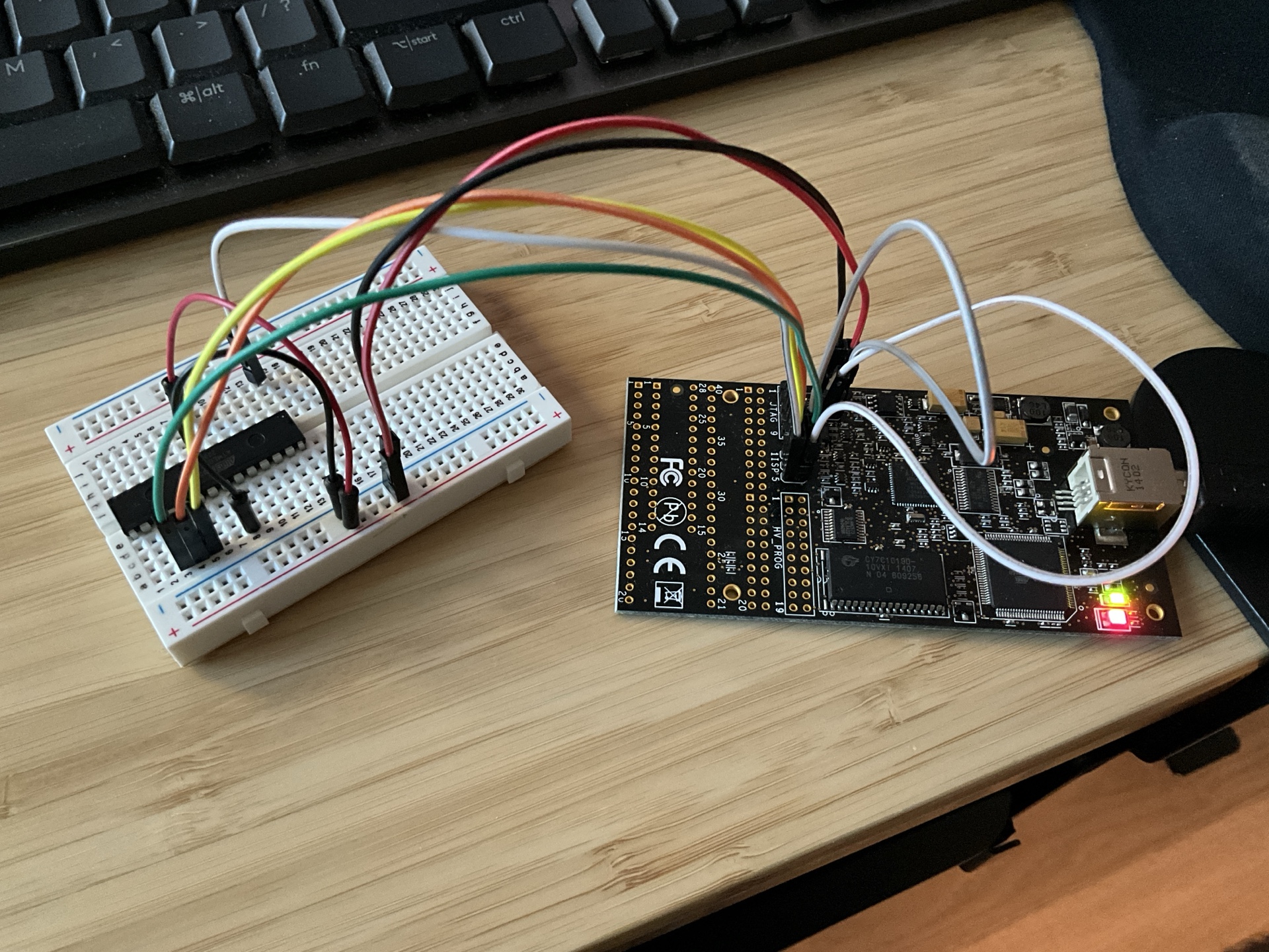
I went a little fancier here and used AVR Dragon. Conceptually, this isn’t much different from using an Arduino as a programmer. All I used was a breadboard to plug in my ATmega328p and I wired SPI plus a few other pins required for flashing (power, of course, and also pins like the reset pin). I’m sure AVR Dragon has a lot of other more advanced features that Arduino can’t pull off, but none of those were necessary for this experiment, and I have a Dragon lying around from ages ago.
I first mentioned AVR Dragon in my blog earlier when philosophizing about making a Linux-ready PCB.
First, to check whether I’m connected correctly with my microcontroller via AVR Dragon, I ran this:
sudo avrdude -c dragon_isp -P usb -p m328p -v -B 10This was the output:
$ sudo avrdude -c dragon_isp -P usb -p m328p -v -B 10 avrdude: Version 7.1 Copyright the AVRDUDE authors; see https://github.com/avrdudes/avrdude/blob/main/AUTHORS System wide configuration file is /etc/avrdude.conf User configuration file is /root/.avrduderc User configuration file does not exist or is not a regular file, skipping Using Port : usb Using Programmer : dragon_isp Setting bit clk period : 10.0 avrdude: usbdev_open(): found AVRDRAGON, serno: 00A200067887 JTAG ICE mkII sign-on message: Communications protocol version: 1 M_MCU: boot-loader FW version: 255 firmware version: 6.11 hardware version: 1 S_MCU: boot-loader FW version: 255 firmware version: 6.11 hardware version: 7 Serial number: 00:a2:00:06:78:87 Device ID: AVRDRAGON AVR Part : ATmega328P Chip Erase delay : 9000 us PAGEL : PD7 BS2 : PC2 RESET disposition : possible i/o RETRY pulse : SCK Serial program mode : yes Parallel program mode : yes Timeout : 200 StabDelay : 100 CmdexeDelay : 25 SyncLoops : 32 PollIndex : 3 PollValue : 0x53 Memory Detail : Block Poll Page Polled Memory Type Alias Mode Delay Size Indx Paged Size Size #Pages MinW MaxW ReadBack ----------- -------- ---- ----- ----- ---- ------ ------ ---- ------ ----- ----- --------- eeprom 65 20 4 0 no 1024 4 0 3600 3600 0xff 0xff flash 65 6 128 0 yes 32768 128 256 4500 4500 0xff 0xff lfuse 0 0 0 0 no 1 1 0 4500 4500 0x00 0x00 hfuse 0 0 0 0 no 1 1 0 4500 4500 0x00 0x00 efuse 0 0 0 0 no 1 1 0 4500 4500 0x00 0x00 lock 0 0 0 0 no 1 1 0 4500 4500 0x00 0x00 signature 0 0 0 0 no 3 1 0 0 0 0x00 0x00 calibration 0 0 0 0 no 1 1 0 0 0 0x00 0x00 Programmer Type : DRAGON_ISP Description : Atmel AVR Dragon in ISP mode Vtarget : 5.0 V SCK period : 10.37 us avrdude: AVR device initialized and ready to accept instructions avrdude: device signature = 0x1e950f (probably m328p) avrdude done. Thank you.To finally flash with avrdude, I used this:
sudo avrdude -c dragon_isp -P usb -p m328p -v -B 10 -U flash:w:program.hexThe output was the same, except that it had this at the end as well:
avrdude: Note: flash memory has been specified, an erase cycle will be performed. To disable this feature, specify the -D option. avrdude: erasing chip avrdude: reading input file program.hex for flash with 274 bytes in 1 section within [0, 0x111] using 3 pages and 110 pad bytes avrdude: writing 274 bytes flash ... Writing | ################################################## | 100% 0.60 s avrdude: 274 bytes of flash written avrdude: verifying flash memory against program.hex Reading | ################################################## | 100% 0.49 s avrdude: 274 bytes of flash verified avrdude done. Thank you.The flags here should be self-explanatory for the most part. The -B flag is a less obvious one, however. It controls the data transfer speed, as I understand it. I was getting errors with the default transfer speed and some Googling revealed that this could help. After I applied it, things worked out normally.
I believe the programmer’s clock is just significantly higher than the microcontroller’s internal clock for the default speed to work correctly, or I imagine the breadboard-based connection for flashing could be a bottleneck. Either way, as mentioned, simply specifying a low enough -B flag worked.
Running the system
The final system is very simple:
- The microcontroller is powered by 5V, while the cooler gets 12V. The 12V is obtained from a DC power source that plugs into the wall outlet, and there is a conversion from 12V down to 5V.
- The cooler connector, in addition to power and ground connections, gets the PWM signal from the microcontroller output pin to control the cooling intensity.
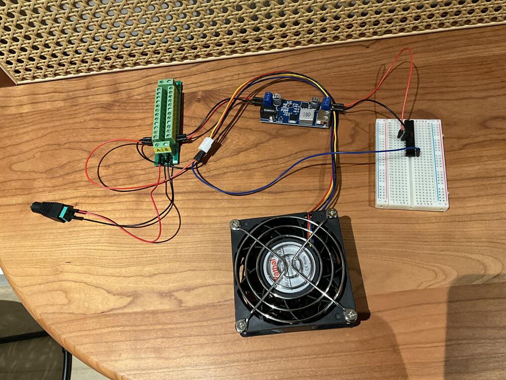
You can see in the video below how the cooler starts moving as the cooling intensity picks up.
Conclusion
In my view, this is a pretty cost-effective way to play with embedded systems. There is some price overhead in getting the hardware to do the flashing, but again, an Arduino or a minimal Raspberry Pi should do the trick (and it’s a one-off price for playing with all AVRs). It uses free and open-source software to do the compiling and flashing (and simulation if you want to do that before committing to buying hardware; check this for pointers).
Some follow-up experiment ideas:
- Connect the 4th pin from the cooler to monitor the cooler rotations as well.
- Send commands from your computer or phone via UART (should be possible with a USB-to-TTL adapter cable) to control the intensity that way, instead of just cycling.
- Put together your own microcontroller PCB board in the end! Check the guide for making a Linux-ready PCB; this experiment would be significantly simpler.
I hope this was a useful exploration.
Please consider following on Twitter/X and LinkedIn to stay updated.