.png)

Introduction
The iron and steel making industry is the largest industrial emitter of CO2, responsible for approximately 7 % of the total global CO2 emissions1. Steel is produced from ore containing magnetite (Fe3O4) or hematite (Fe2O3) processed through the integrated blast furnace reduction and basic oxygen furnace steel making route2 at high temperatures. Burning coke, which acts as both an energy source and the reducing agent in the blast furnace reduction process, is the major contributor of CO2 emissions. While innovative iron ore reduction approaches have largely failed to replace blast furnace reduction to date, using H2 and renewable electricity could eliminate the need for carbon-based energy carriers, only producing the environmentally friendly byproduct H2O. However, the thermodynamic restriction imposes challenges as the reduction of Fe3O4 to FeO by H2 requires temperatures higher than 900 K and further reduction of FeO to Fe requires excess H2 even at higher temperatures3. Non-thermal hydrogen plasmas have recently been suggested as promising solutions to overcome these thermodynamic limitations4. Short-lived highly energetic plasma-produced species of hydrogen such as excited species and hydrogen radicals are hypothesized to enable non-thermal plasma reduction by lowering the activation energy of the reduction process. Nonetheless, the fundamental processes and mechanisms underpinning the reactions and transport, likely involving very distinctive pathways compared to the thermal reduction in H2, remain unclear. While many processes for iron reduction occurring on micrometer and millimeter scales, the usually highly inhomogeneous structure of such large-scale materials combined with the limited transport length scales of the short-lived reactive plasma-produced species motivated us to focus on a nanoscale investigation of the reduction of magnetite (Fe3O4) nanoparticles to study the underpinning reactions and for conditions where the transport is very fast.
Operando, or in situ, transmission electron microscopy (TEM), where nm scale changes of materials are readily identifiable, appears to be an excellent approach to study plasma-enabled iron oxide reduction. Operando TEM has been successfully used for studies of nanoparticle formation, growth and self-organization5,6,7,8,9, as well as for interactions between nanomaterials and gas or liquid10,11,12. However, there is no operando TEM with such plasma capability at the nm scale available. The challenge is sustaining atmospheric pressure plasma inside the TEM, requiring high voltages (hundreds of V), while finding a trade-off between electrode spacing to be sufficiently large for plasma generation and small enough for electron transparency for imaging. Furthermore, part of the gas cell should be a thin membrane to permit the electron beam to image the sample, which is required to remain intact against etching and thermal strain caused by the plasma. An earlier report showing an integration of argon plasma to TEM13 provided a blueprint that such plasma-incorporated operando TEM is achievable with a spatial resolution of <100 nm. Results from the implementation of scanning electron microscope (SEM)14,15 are also encouraging. However, both these studies still do not provide nanometer resolution, and the SEM approach does not allow the plasma to be operated at atmospheric pressure, as relevant for practical iron ore reduction.
Here, we report on the development of an operando plasma TEM technique with a spatial resolution of ~1 nm. This capability enabled the direct and real-time observations of non-thermal hydrogen plasma-driven reduction of Fe3O4 at atmospheric pressure, as evidenced by the shrinkage and the crack formation of magnetite nanoparticles. Tracking real-time size changes of magnetite nanoparticles allowed us to identify the rate-controlling process between transport and reactions and obtain reaction rates, which had remained ambiguous. The result can aid more accurate model development of larger scale plasma-enabled reduction processes. These findings demonstrate the potential of the operando plasma TEM technique for investigating mechanisms of other plasma-material interactions, such as plasma-enhanced catalysis or nanomaterial synthesis, where nanoscale observations are crucial.
Results
An operando plasma TEM capability was developed by building a dedicated TEM holder with an atmospheric plasma-cell that is compatible with commercial TEMs (Fig. 1a). The plasma cell is designed to generate and sustain an atmospheric pressure DC glow discharge plasma in the fully enclosed cell. The cell consists of two Si-based chips with electron-transparent a-SiNx windows, separated by spacers (strips) (Fig. 1a). For stable plasma operation, a gap of about 60 µm between cathode and anode chips is used. The metallic electrodes are designed with different geometries, hole type (cathode) and mesh type (anode). The hole type design for the cathode is to maximize the area of the electrode for robustness against etching and thermal strain, while having sufficient areas of openings for TEM imaging. The electrode chips are passivated with SiO2 layers (Fig. 1b) to prevent unwanted current leakage. The a-SiNx membranes are sufficiently thin (50 nm) for electron transparency needed for TEM imaging. This plasma cell allows the direct optical detection of the plasma in the cell (Fig. 1c), which simplifies testing of the cell before operando TEM measurements. Plasma could be sustained for more than an hour without membrane fracture. The magnetite nanoparticles are placed on the anode chip (on the a-SiNx membrane) and are observed through common openings on the anode and cathode electrodes (Fig. 1d).

a An overview of the custom plasma holder and holder tip assembly, consisting of a cathode chip, an anode chip, and spacers (60 \({{\rm{\mu }}}{{\rm{m}}}\) thickness). The tungsten electrodes configurations of both the cathode and the anode are presented in the right upper corner. b A schematic side cross section view of the plasma cell. c An optical image (top view) of a He plasma operation inside the plasma holder (scale bar denotes 1 mm). d A low magnification microscopic view of the holder (scale bar denotes 5 \({{\rm{\mu }}}{{\rm{m}}}\)) without plasma ignited. The bright circular area is an opening where the tungsten electrode is not deposited. Magnetite nanoparticles are placed at the anode chip on the top of the a-SiNx membrane (see inset of d, scalebar = 20 nm). A negative DC voltage was applied to the cathode (b). He + 0.5 % H2 gas mixture with a flow rate of 10 sccm was used for experiments. Plasma could be sustained more than an hour while maintaining vacuum and membrane integrity as in c.
When magnetite nanoparticles are exposed to a He + 0.5 % H2 plasma (56 mW) inside the TEM, they first reduce in size and then crack, as can be seen in a set of sequential images in Fig. 2a (see particles with arrows). These changes in the nanoparticles are directly related to the presence of H2 gas in the cell, since exposure of particles to only He plasma with similar power (60 mW) shows no changes in the morphology (see Figure S1a). This suggests that reactive species of helium (e.g., helium metastables) do not directly contribute to the changes in morphology. Furthermore, the effects of nanoparticle charging and ion sputtering are negligible. It was also confirmed that the low-dose electron beam (13 e− \({{{\text{\AA}} }}\)−1s−1) in the He + 0.5 % H2 environment for TEM imaging does not lead to any particle morphology changes (see Figure S1b). The compositional analysis of size-reduced and cracked magnetite nanoparticles shows that there is a dramatic reduction of oxygen contents in nanoparticles after the exposure to He + 0.5 % H2 plasma, based on energy dispersive X-ray (EDX) elemental maps and 1-D profiles obtained in scanning-TEM (STEM) mode (Fig. 2b). The high-resolution TEM images obtained before and after plasma exposure (Fig. 2c) also indicate the reduction and phase change from Fe3O4 to Fe. It should be noted that FeO (wüstite), typically presents as an intermediate species in high temperature reductions (>840 K)16,17,18, is not observed here. The quantification of the oxygen reduction, using 1-D profiles from Fig. 2b, shows that most of the original Fe3O4 is reduced to Fe, with the O-to-Fe intensity ratio decreasing from 0.75 to 0.09 (Fig. 2d). This corresponds to a reduction degree of about 0.88 (i.e., 88 % of oxygen removed). The average particle diameter (Fig. 2e) decreases by 7 % (from 29.6 nm to 27.6 nm) due to the crystal shrinkage, eventually leading to particle cracking. The particle cracking due to phase changes has been reported in literature for silicon nanoparticles after lithiation19 or gibbsite crystallite after calcination20. The reduction of magnetite nanoparticles and resulting crack formations and size shrinkage exhibit a power threshold effect (see SI-Inhomogeneity of He+H2 plasma and Figure S1c) likely correlated with the variations in species fluxes and temperature impacting plasma induced reactions on the nanoparticle.
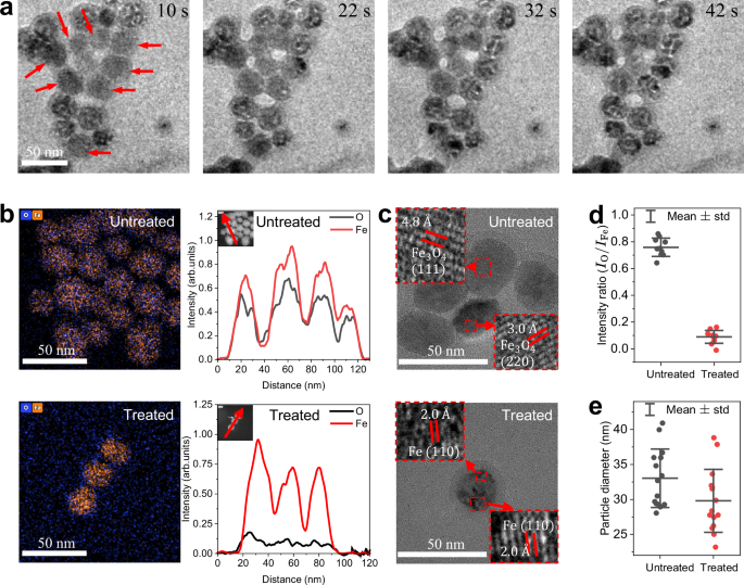
a Operando sequential images of nanoparticles treated by He + 0.5 % H2 plasma (56 mW). For imaging, a relatively low electron dose rate is used (13 e− \({{{\text{\AA}} }}\)−1s−1). b EDX-mapped images and corresponding 1-D profiles (see inset) of net signals of untreated and treated nanoparticles by He + 0.5 % H2 plasma. c High-resolution TEM images of untreated and treated nanoparticles by He + 0.5 % H2 plasma with magnified insets. d Statistics of integrated net intensity ratios of untreated and treated nanoparticles measured from at least 10 particles for each case. The degree of reduction is calculated based on the average intensity ratio change. e Statistics of particle sizes of untreated and treated nanoparticles from the main experiment in a and from SI-Additional operando experiments. The particle sizes just before crack formation are measured for treated samples. Note that some nanoparticles in a are already cracked due to the pre-treatment outside TEM ( ~ 10 s) to optically locate the constricted plasma (see Method-Operando plasma experiment). Scale bars denote 50 nm.
Discussion
The direct reduction of magnetite to iron by H2 can be expressed as:
$${{\rm{F}}}{{{\rm{e}}}}_{3}{{{\rm{O}}}}_{4}+4{{{\rm{H}}}}_{2}\to 3{{\rm{Fe}}}+4{{{\rm{H}}}}_{2}{{\rm{O}}}.$$
(R 1)
Above 840 K, this reaction proceeds through the formation of the intermediate FeO and is rate-limited by the FeO to Fe reduction step16. However, below 840 K3,4 the reaction (R1) has a positive Gibbs free energy (\(\Delta {G}_{r}^{0} > 0\)). Since the gas temperature of the plasma does not exceed 700 K (see SI-Temperatures), we conclude that the plasma conditions are not favorable for thermal reduction driven by H2. To assess the potential impact of thermal reduction reactions, another set of measurements were performed where nanoparticles were exposed to an identical He + 0.5 % H2 gas mixture outside the TEM at the similar temperature observed in the plasma in the TEM, and it showed no detectable Fe3O4 reduction (see SI-Thermal reduction control experiment and Figure S5). We have not found experimental evidence supporting that the ligand layer of nanoparticles impacts the reduction.
Plasma leads to the formation of the hydrogen radicals (H•), positively charged ions (H+, H2+, or H3+), and electronically excited species (H*, H2*) for which the reduction reaction of any form of iron oxide is thermodynamically favorable (\(\Delta {G}_{r}^{0}\ll \, 0\)) even at room temperature4:
$${{\rm{F}}}{{{\rm{e}}}}_{x}{{{\rm{O}}}}_{{{\rm{y}}}}+2y\left({{\rm{H}}}^{\bullet},{{{\rm{H}}}}^{*} ,\frac{1}{2}{{{\rm{H}}}}_{2}^{*}\right)\to x{{\rm{Fe}}}+y{{{\rm{H}}}}_{2}{{\rm{O}}},$$
(R 2)
or,
$${{\rm{F}}}{{{\rm{e}}}}_{x}{{{\rm{O}}}}_{{{\rm{y}}}}+2y\left(\frac{1}{{{\rm{n}}}}{{{\rm{H}}}}_{{{\rm{n}}}}^{+}\right)+\frac{2y}{n}{{{\rm{e}}}}^{-}\to x{{\rm{Fe}}}+y{{{\rm{H}}}}_{2}{{\rm{O}}}\left({{\rm{n}}}=1,2,3\right).$$
(R 3)
In the experimental setup used here, the contribution of positively charged ions is expected to be minimal since particles are placed at the anode side (positive ions drift towards the cathode). Electronically excited hydrogen (\({{{\rm{H}}}}^{*}\), \({{{\rm{H}}}}_{2}^{*}\)) is also unlikely to play a significant role since the densities of H*and H2* are several orders of magnitude (>105) lower than the density of ground state H• due to their much shorter lifetime and lower production rates21,22. Hence, in this setup, H• is expected to enable the magnetite nanoparticles reduction.
The electron temperature in our experiments is estimated to be 12 eV (see SI-Temperatures), which is higher than typical values in the positive column of glow discharges21,23 due to the small scale of plasma. At this electron temperature, helium metastables (He*) predominantly dissociate H2, resulting in 100 times faster dissociation than electron-impact reactions (see SI-Hydrogen dissociation mechanism in He+H2 plasma). Furthermore, the characteristic timescale of the He*-induced H2 dissociation is much shorter than that of He* diffusion to the anode. Therefore, most He* is lost due to the H2 dissociation before reaching nanoparticles on the anode electrode. Note that even when He-only plasma is used (Figure S1 a) where a significant flux of He* is expected to impinge on the nanoparticles, we did not observe oxide reduction suggesting the lack of reducing ability of He*.
The rate of H• production by the He*-induced dissociation is estimated as ~1027 m−3 s−1, resulting in an estimated H• flux toward the anode of ~1024 m−2s−1 and a corresponding H• fluence of ~1010 to each particle in 10 s (see SI- Hydrogen density and fluence determination for details). Considering that each particle has ~105 oxygen atoms, an abundant amount of H• is available for the reduction. Note that the thermal dissociation of hydrogen molecules at 673 K24, which is the upper limit of the estimated temperature of the plasma, yields an H• density of ~ 1011 m−3, which results in a negligible fluence of H• to have any significant impact on the reduction of the nanoparticles.
Hence, the overall reduction rate of magnetite nanoparticles enabled by H• (reaction R2) is expected to be controlled by one of the following solid/interfacial kinetic processes: gas-solid reactions, species diffusion in the solid phase of the particle or nucleation. To elucidate the rate-controlling step in the nanoparticle reduction, we quantified the time evolution of the reduction degrees from the operando TEM images in Fig. 2a and in two additional operando experiments (see SI-Additional operando experiments). The averaged volumes of the particles in these experiments are tracked for 100 s (Fig. 3a). The reduction degree, \(R\)(t), is estimated from the particle volume, \(R\left(t\right)=C\left(1-\frac{V(t)}{{V}_{0}}\right)\) (Method-Reduction degree estimation from particle volume) as the particle volume shrinks with the removal of oxides as shown in Fig. 2e. The integral form of the reaction models25, g(R(t)), is expressed with g(R(t)) = kappt, where kapp is an apparent rate constant. The experimentally obtained g(R(t)) of different reaction models is fitted with a line (see SI-Reduction model fitting results), before the cracking time of the nanoparticles. As a result, the shrinking-core reaction model (Fig. 3b), which assumes the overall rate of the reduction is controlled by the reduction reaction at the Fe – Fe3O4 phase boundary, has the highest correlation factor among the fitted results for the three groups of operando plasma experiments. We exclude the homogeneous reaction model as H• cannot diffuse throughout the entire iron oxide particle on the timescale of the observed reduction (see SI- Reduction model fitting results). This outcome suggests that the diffusion of the reactant H•, or the product, H2O, through the reduced Fe is faster than the reduction reaction (R2) at the Fe-Fe3O4 boundary, which is indicated by the lower correlation factor of the shrinking-core diffusion model (see also SI- Reduction model fitting results). The implication here is consistent with the diffusion time scales of H2 and H2O through the Fe layer, (\({\tau }_{{{{\rm{H}}}}_{2}{{\rm{O}}},{{\rm{Fe}}}}\) < 10−13 s), estimated based on reported equimolar diffusion coefficients of H2 and H2O26. Since H• diffuses as fast (or even faster) as H227,28 through metallic membranes, we anticipate a similar diffusion timescale for H•. Note that the reported diffusion coefficient has the same order of magnitude as the corresponding gaseous diffusion coefficient since the Fe layer reduced from Fe3O4 has a significantly lower resistance to diffusion compared to crystalline Fe29.
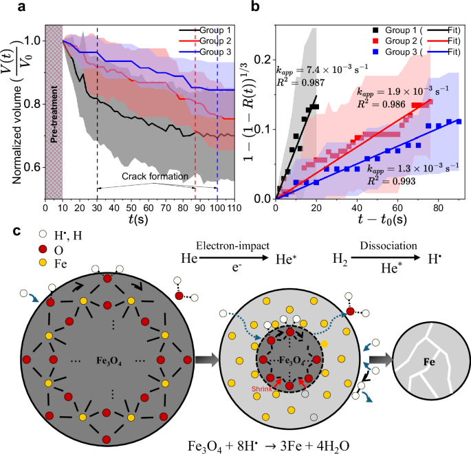
a The averaged volume of selected magnetite nanoparticles from group 1 (arrows in Fig. 2a), group 2, and group 3 (see arrows in SI-Additional operando experiments) as a function of time (t) during the He+ 0.5 % H2 plasma treatment. The averaged timing of crack formation for each group is indicated by a dashed vertical line. b A shrinking-core reaction model fitting of the experimental results with the y-axis corresponding to g(R(t)). Note that the nanoparticles were pre-treated (\({t}_{0}=10{\ {\rm{s}}}\)) outside the TEM to optically locate the constricted plasma (see Method-Operando plasma experiment), and this is indicated in a with a meshed area between 0 s and 10 s. Shaded areas in a and b correspond to ±1 standard deviation around the mean. The apparent rate constants (kapp) and correlation factors (\({R}^{2}\)) obtained from the fits are also provided together. c A schematic representation of the non-thermal reduction process proposed in this work.
The apparent rates of reduction of magnetite nanoparticles treated by plasma for group 1,2, and 3 are (7.4\(\pm\)0.3)\(\times\)10−3 s−1, (1.88\(\pm\)0.04)\(\times\)10−3 s−1, (1.3\(\pm\)0.3)\(\times\)10−3 s−1, respectively. These obtained rates differ by a factor of 5 despite the similar plasma power (56, 58, and 41 mW, respectively). This is likely due to variations in the plasma power density, depending on the degree of plasma constriction or the location of particles relative to the center of the constricted plasma as shown in SI-Inhomogeneity of He+H2 plasma. We hypothesize that higher temperature for higher power densities can facilitate the reduction which is endothermic, as the reduction is reaction-controlled at the phase boundary. In addition, the H• recombination at the surface of particles30,31, which can potentially reduce the available H• for reduction, is exothermic and slower at higher temperatures. Meanwhile, the apparent rate constant of thermal reduction by H2 at the maximum temperature of the operando plasma experiment (see SI-Thermal reduction control experiment) is at least two orders of magnitude smaller than the rate observed during the operando experiment, consistent with the hydrogen radical-enabled non-thermal reduction.
The proposed mechanism for He + 0.5 % H2 plasma-driven iron oxide reduction is shown in Fig. 3c. The rate-controlling step is the reduction of Fe3O4 to Fe by H• at the phase boundary of the shrinking core. In thermal H2 reduction at elevated temperatures the diffusion of Fe2+ or Fe3+ through the FeO layer and the diffusion of oxygen from the magnetite through the iron layer are suggested to be critical17. However, in the presence of an abundant amount of H• at temperatures below 700 K, H• quickly diffuses through the reduced iron layer to react with the oxide at the Fe – Fe3O4 interface. The unreacted core consisting of Fe3O4 shrinks as a new iron layer forms at the phase boundary. When about half of the oxygen atoms are removed from the nanoparticle, the nanoparticle is cracked by crystal shrinkage.
To further support these findings, additional sets of experiments were conducted, where the production of H• was achieved by a high-dose TEM electron beam (190 e− \({{{\text{\AA}} }}\)−1s−1) in a He + 0.5 % H2 environment. The oxide reduction of nanoparticles was confirmed by compositional analysis, even at room temperature conditions, due to nearly negligible temperature increase provoked by electron beam irradiation on the a-SiNx membrane32,33. This implies, again, that the reduction of magnetite nanoparticles is a non-thermal process and is enabled by the hydrogen radical, H•. The dynamic particle size analysis here shows the same rate-controlling mechanism (shrinking-core reaction model) is valid and the apparent rate constant of kapp = 9.0\(\times\)10-3 s−1 is in the same order with the rate constants observed for plasma enabled reduction (see Figure S10 for details).
In conclusion, we report on the direct observation of plasma-driven oxide reduction in Fe3O4 nanoparticles using operando plasma TEM. This approach enables time-dependent direct imaging of particles with nanometer-level details, which was used to directly observe particle cracking and measure size reduction as well as the kinetics of Fe3O4 reduction in a He + 0.5 % H2 plasma. The operando measurements allowed us to identify the rate-controlling step and determine the apparent rate constant which is two orders of magnitude larger than that of H2 thermal reduction at the same conditions. While our study focuses on nanoparticles, iron ore often consists of porous, micrometer-scale structures, which may introduce differences in transport and reduction kinetics. In macroscopic systems, transport limitations become more significant due to the larger transport length scale. Additionally, the presence of mesopores in bulk iron ore can enhance penetration and the availability of reactive species. Despite these differences, our contribution provides fundamental insights into the reduction mechanisms where transport in the solid phase is exceedingly fast and one can uniquely explore reactions. The gained understanding of the underlying processes is applicable to larger systems and can provide methodological guidance.
Such operando plasma TEM capability can be utilized for probing plasma processes and their rates at the nanoscale. Non-thermal plasmas have been implemented to process, treat, synthesize or functionalize diverse materials especially for heat-sensitive materials including catalysts, biofilms, and nanoparticles34,35. While the number of plasma applications keeps increasing, the science of the underlying processes remains lagging due to a lack of operando diagnostics on the relevant nanometer length scales. While results from this study are encouraging for plasma-reduction of iron ore and plasma catalysis research which also extensively uses iron oxide nanoparticles36,37,38, the operando plasma TEM has the potential to extend the diagnostic capabilities to other challenging fields such as plasma-induced nanomaterial synthesis39, and potentially, even virus inactivation40.
Methods
Plasma holder and gas cell design
The gas cell described in this manuscript is inspired by the work of Tai et al.13 and is composed of two electrode chips, namely cathode (4.86 mm\(\times\) 6.35 mm) and anode chips (5.6 mm \(\times\) 5.6 mm). The custom plasma holder and plasma chips were manufactured by Hummingbird Scientific. The two electrode (cathode and anode) chips inside the plasma gas cell have conducting electrical paths and were sealed by O-rings from the vacuum ( ~10-7 mbar) of the microscope column. Silicon nitride membranes (50 nm thickness) and a silicon oxide dielectric film (5 μm thickness) were stacked on both chips. The silicon oxide dielectric film was for passivation to prevent a current leakage away from the electrodes to the silicon substrate (Fig. 1). Spacers (titanium and peek) of 60 μm thickness were placed between the upper and lower chips, where the titanium spacer enables electric contact with the conducting electrode on the upper chip. On the viewing window (30µm × 800µm), tungsten electrodes (140 \({{\rm{\mu }}}{{\rm{m}}}\times\) 900 \({{\rm{\mu }}}{{\rm{m}}}\) \(\times\) 100 nm) are deposited (hole type and mesh type, see Fig. 1a) for generating the plasma. The mesh type electrode (5 µm trace and 10 µm openings) is used for the anode chip. The hole type electrode (with 1.5 μm diameter holes with 7.5 µm spacings) is for the cathode chip. The design was to enhance the mechanical robustness of the electrode and reduce the impact of membrane etching of the cathode. Also, the larger effective area of the tungsten electrode at the upper chip could facilitate the heat dissipation, preventing thermal strains in the membrane. The sealing of the plasma cell was secured by Viton O-rings between the anode chip and metal holder and between the two chips. The distance between the two chips (60 µm) is close to the Paschen minimum breakdown voltage41 to enable us to minimize the applied voltage (350–500 V).
Operando plasma experiment
The custom operando plasma holder with assembled plasma cell at the tip was first inspected under an optical microscope (Leica M165C) for the proper alignment of the two windows. It was then placed into a vacuum pump station (PFEIFFER, HI Cube 80 Eco) to check sufficient sealing required by the TEM. The pressure decrease speed should satisfy <6\(\times\)10−6 mbar within 5 min with 1500 Hz rotor. The inspected holder is connected to a high voltage power supplier (Spellman SL 6 PN 300) and ground. A \(1{{\rm{M}}}\Omega\) resistor is connected between the power supply and the cathode connection of the holder in series (see Fig. 1b). The applied voltage (\({V}_{a}\)) and the voltage across the plasma (\({V}_{p}\)) are measured by high voltage probes (Tektronix P6015A, 1000X) connected to an oscilloscope (RIGOL, DS1204B). The plasma power was calculated by multiplying the plasma current (\({I}_{p}=({V}_{a}-{V}_{p})/1{{\rm{M}}}\Omega\)) by the voltage across the plasma. The gas flow was controlled by MFC controllers (MKS, 10 and 20 standard cubic centimeter (sccm)) and a readout (MKS 247). The total flow rate was kept constant as 10 sccm throughout the work. Two gas cylinders with pure helium and hydrogen 4 % balance with helium were used to dilute the H2 content. We used the 0.5 % H2 for the main experiments, minimal to avoid membrane fracture (see SI-Inhomogeneity of He+H2 plasma). After flushing the gas for 10 min to remove existing impurities, a short pre-treatment ( ~ 10 s) was performed to visually check the position of the constricted plasma (see SI-Inhomogeneity of He+H2 plasma) since locating the position of the plasma is not feasible inside the TEM. An FEI Tecnai T12 transmission electron microscope was utilized for the operando experiments with an acceleration voltage of 120 keV. The low-dose electron beam and low magnification (spot size 6) were used to locate the viewing window of the gas cell and locations of our interest at first, and then higher-dose electron beam (spot size 3) was used for the series imaging with higher magnification. The magnification was kept at \(\times\)67k with a C2 aperture opening of ~36 %. The electron dose rate was ~13 e− \({{{\text{\AA}} }}\)−1s−1. We did not see changes in the discharge current and breakdown voltage when introducing the electron beam, suggesting negligible alteration of plasma characteristics by the low dose electron beam. The series images were obtained using an exposure time of 0.1 s.
Sample preparation
We used iron oxide nanoparticles in colloidal form (Fe3O4, 30 nm average diameter, Sigma-Aldrich) to enable good adhesion and dispersion of nanoparticles on the membrane. The precursor solution was prepared by ten times dilution of the purchased solution. The anode chip was cleaned with an air plasma (Fischione Instruments, model 1070 Nanoclean) for 20 seconds to make the membrane hydrophilic before applying a 0.7 µL droplet of the prepared solution on the membrane, which immediately became a thin film. This led to well-dispersed nanoparticles on the film. The anode chip was dried for 1 hour under a ventilation hood before assembly of the plasma cell.
Ex situ STEM/EDX
For the EDX analysis, a Thermo Fisher Talos F200X TEM was used (200 keV). A tomography holder (Hummingbird Scientific) was used to hold the anode chip containing the magnetite nanoparticles after the operando experiments. The tomography holder was tilted 23° to make a position of interest offset upwards from the plane of zero-tilt. This was to avoid the shadowing of the dispersive signals coming from the chip itself. The EDX signals were pre-filtered before background correction by an average filter with kernel size between 13 and 21. Quantitative EDX analysis was based on the 1-D net intensities as shown in Fig. 2b. At least ten particles were counted for each case for the statistical analysis shown in Fig. 2d. The reduction degree, R, can be defined as the ratio of oxygen atoms removal to the initial oxygen content in each particle. Since the net intensity signal (I) of an element is proportional to the mole fraction of the element, we can express R as
$$R=1-\frac{{I}_{{\rm{O}}}/{I}_{{{\rm{Fe}}}}}{{I}_{{\rm{O}}}/{I}_{{{\rm{Fe}}}}{|}_{{untreated}}},$$
(1)
where \(I\) denotes the net EDX intensity signal of an element.
Reduction degree estimation from the particle volume
The nanoparticle volume decreases with the oxide reduction29. The particle size was measured by fitting particles into rectangles. The width and height of the particles were averaged as a particle diameter. All the particles are assumed to be spherical, and the volume is calculated accordingly. The reduction degree (R(t)) is estimated as follows:
$$R(t)=C\left(1-\frac{V(t)}{{V}_{0}}\right)$$
(2)
where \(V\), \({V}_{0}\) and \(C\) denote particle volume, particle initial volume and normalization coefficient which is expressed by
$$C=\frac{1}{1-\frac{3{v}_{{Fe}}}{{v}_{F{e}_{3}{O}_{4}}}}$$
(3)
where \(v\) denotes molar volume. For \(\frac{V}{{V}_{0}}\) equal to 0.47, the reduction degree R is 1.
Reporting summary
Further information on research design is available in the Nature Portfolio Reporting Summary linked to this article.
Data availability
Relevant data supporting the key findings of this study are available within the article and the Supplementary Information (SI) file. The raw data supporting this study is provided in Source Data file. Source data are provided with this paper.
References
Xu, R. et al. Plant-by-plant decarbonization strategies for the global steel industry. Nat. Clim. Chang. 13, 1067–1074 (2023).
Ma, K., Deng, J., Wang, G., Zhou, Q. & Xu, J. Utilization and impacts of hydrogen in the ironmaking processes: a review from lab-scale basics to industrial practices. Int. J. Hydrog. Energy 46, 26646–26664 (2021).
Sabat, K. C. & Murphy, A. B. Hydrogen plasma processing of iron ore. Met. Mater. Trans. B 48, 1561–1594 (2017).
Sabat, K. C., Rajput, P., Paramguru, R. K., Bhoi, B. & Mishra, B. K. Reduction of oxide minerals by hydrogen plasma: an overview. Plasma Chem. Plasma Process 34, 1–23 (2014).
Zhang, Y., Keller, D., Rossell, M. D. & Erni, R. Formation of Au nanoparticles in liquid cell transmission electron microscopy: from a systematic study to engineered nanostructures. Chem. Mater. 29, 10518–10525 (2017).
Uematsu, T. et al. Atomic resolution imaging of gold nanoparticle generation and growth in ionic liquids. J. Am. Chem. Soc. 136, 13789–13797 (2014).
Ma, X., Lin, F., Chen, X. & Jin, C. Unveiling growth pathways of multiply twinned gold nanoparticles by in situ liquid cell transmission electron microscopy. ACS Nano 14, 9594–9604 (2020).
Keller, D., Henninen, T. R. & Erni, R. Atomic mechanisms of gold nanoparticle growth in ionic liquids studied by in situ scanning transmission electron microscopy. Nanoscale 12, 22511–22517 (2020).
Woehl, T. J., Evans, J. E., Arslan, I., Ristenpart, W. D. & Browning, N. D. Direct in situ determination of the mechanisms controlling nanoparticle nucleation and growth. ACS Nano 6, 8599–8610 (2012).
Xin, H. L., Niu, K., Alsem, D. H. & Zheng, H. In situ TEM study of catalytic nanoparticle reactions in atmospheric pressure gas environment. Microsc. Microanalysis 19, 1558–1568 (2013).
Simonsen, S. B. et al. Direct observations of oxygen-induced platinum nanoparticle ripening studied by in situ TEM. J. Am. Chem. Soc. 132, 7968–7975 (2010).
Son, Y. et al. In situ liquid phase TEM of nanoparticle formation and diffusion in a phase-separated medium. ACS Appl. Mater. Interfaces 14, 22810–22817 (2022).
Tai, K., Houlahan, T. J., Eden, J. G. & Dillon, S. J. Integration of microplasma with transmission electron microscopy: Real-time observation of gold sputtering and island formation. Sci. Rep. 3, 1325 (2013).
Matra, K., Mizobuchi, Y., Furuta, H. & Hatta, A. Local sputter etching by micro plasma jet in SEM. Vacuum 87, 132–135 (2013).
Grünewald, L. et al. In situ plasma studies using a direct current microplasma in a scanning electron microscope. Adv. Mater. Technol. 9, 2301632 (2024).
Spreitzer, D. & Schenk, J. Reduction of iron oxides with hydrogen—a review. steel Res. Int. 90, 1900108 (2019).
Ma, Y. et al. Hierarchical nature of hydrogen-based direct reduction of iron oxides. Scr. Mater.213, 114571 (2022).
Heidari, A., Niknahad, N., Iljana, M. & Fabritius, T. A Review on the kinetics of iron ore reduction by hydrogen. Materials, vol. 14, Art. no. 24, (2021).
Liu, X. H. et al. Size-Dependent Fracture of Silicon Nanoparticles During Lithiation. ACS Nano 6, 1522–1531 (2012).
Zhang, J., Ge, L., Chen, Z.-G., Boom, E. & Zhu, Z. Cracking Behavior and Mechanism of Gibbsite Crystallites during Calcination. Cryst. Res. Technol. 54, 1800201 (2019).
Farouk, T., Farouk, B., Staack, D., Gutsol, A. & Fridman, A. Modeling of direct current micro-plasma discharges in atmospheric pressure hydrogen. Plasma Sources Sci. Technol. 16, 619 (2007).
Liu, D.-X. et al. A theoretical insight into low-temperature atmospheric-pressure He+H2 plasmas. Plasma Sources Sci. Technol. 22, 055016 (2013).
Wang, Q., Economou, D. J. & Donnelly, V. M. Simulation of a direct current microplasma discharge in helium at atmospheric pressure. J. Appl. Phys. 100, 023301 (2006).
Langmuir, I. The dissociation of hydorgen into atoms [PART II.] Calculation of the degree of the dissociation and the heat of formation. J. Am. Chem. Soc. 37, 417–458 (1915).
Khawam, A. & Flanagan, D. R. Solid-state kinetic models: basics and mathematical fundamentals. J. Phys. Chem. B 110, 17315–17328 (2006).
Olsson, R. G. & McKewan, W. M. Diffusion of H2-H2O through porous iron formed by the reduction of iron oxides. Metall. Trans. 1, 1507–1512 (1970).
Livshits, A. I., Notkin, M. E. & Samartsev, A. A. Physico-chemical origin of superpermeability — Large-scale effects of surface chemistry on ‘hot’ hydrogen permeation and absorption in metals. J. Nucl. Mater. 170, 79–94 (1990).
Zheludkevich, M. L. et al. Superpermeability’ and ‘pumping’ of atomic hydrogen through palladium membranes. J. Membr. Sci. 320, 528–532 (2008).
Rau, M.-F., Rieck, D. & Evans, J. W. Investigation of iron oxide reduction by TEM. Met. Trans. B 18, 257–278 (1987).
Baskes, M. I. A calculation of the surface recombination rate constant for hydrogen isotopes on metals. J. Nucl. Mater. 92, 318–324 (1980).
Wood, B. J. & Wise, H. Kinetics of hydrogen atom recombination on surfaces. J. Phys. Chem. 65, 1976–1983 (1961).
Kim, H.-M., Lee, M.-H. & Kim, K.-B. Theoretical and experimental study of nanopore drilling by a focused electron beam in transmission electron microscopy. Nanotechnology 22, 275303 (2011).
Reimer, L. Transmission Electron Microscopy: Physics of Image Formation and Microanalysis. Springer, 2013.
Bruggeman, P. J., Iza, F. & Brandenburg, R. Foundations of atmospheric pressure non-equilibrium plasmas. Plasma Sources Sci. Technol. 26, 123002 (2017).
Adamovich, I. et al. The 2022 Plasma Roadmap: low temperature plasma science and technology. J. Phys. D: Appl. Phys. 55, 373001 (2022).
Audemar, M. et al. Catalytic enrichment of plasma with hydroxyl radicals in the aqueous phase at room temperature. Catal. Sci. Technol. 11, 1430–1442 (2021).
Li, W. et al. Cold atmospheric plasma and iron oxide-based magnetic nanoparticles for synergetic lung cancer therapy. Free Radic. Biol. Med. 130, 71–81 (2019).
Chen, G. et al. Size-dependent activity of iron nanoparticles in both thermal and plasma driven catalytic ammonia decomposition. Ind. Eng. Chem. Res. 61, 11436–11443 (2022).
Kortshagen, U. R. et al. Nonthermal plasma synthesis of nanocrystals: fundamental principles, materials, and applications. Chem. Rev. 116, 11061–11127 (2016).
Aboubakr, H. A. et al. Cold argon-oxygen plasma species oxidize and disintegrate capsid protein of feline calicivirus. PLoS ONE 13, e0194618 (2018).
M. A. Lieberman and A. J. Lichtenberg, Principles of Plasma Discharges and Materials Processing, 2nd ed. Wiley.
Acknowledgements
This work was supported by the U.S. Army DEVCOM ARL Army Research Office (ARO) Energy Sciences Competency, Electrochemistry Program Grant No. W911NF 20-1-0105 and W911NF20−1-0322, which support J.H.N. and P.J.B. The views and conclusions contained in this document are those of the authors and should not be interpreted as representing the official policies, either expressed or implied, of the Army Research Office or the U.S. Government. The U.S. Government is authorized to reproduce and distribute reprints for Government purposes notwithstanding any copyright notation herein. J.H.N. and P.J.B. acknowledge Dr. Stephen Exarhos for experimental support during the initial stage of the device development and Binit Singh for assistance with thermal reduction control experiments. K.A.M. acknowledges supports from NSF through award No. DMR-2309431. Parts of this work were carried out in the Characterization Facility, University of Minnesota, which receives partial support from the NSF through the MRSEC (award No. DMR-2011401) and the NNCI (award No. ECCS-2025124) programs. We thank Dr. Michael Odlyzko for assistance with the TEM measurements.
Ethics declarations
Competing interests
D.H.A. is employed by Hummingbird Scientific, which manufactured the plasma TEM holder and electrode chips used in these experiments. The remaining authors declare no competing interests.
Peer review
Peer review information
Nature Communications thanks Annemie Bogaerts who co-reviewed with Robin De Meyer; and the other anonymous reviewer(s) for their contribution to the peer review of this work. A peer review file is available.
Additional information
Publisher’s note Springer Nature remains neutral with regard to jurisdictional claims in published maps and institutional affiliations.
Supplementary information
Rights and permissions
Open Access This article is licensed under a Creative Commons Attribution-NonCommercial-NoDerivatives 4.0 International License, which permits any non-commercial use, sharing, distribution and reproduction in any medium or format, as long as you give appropriate credit to the original author(s) and the source, provide a link to the Creative Commons licence, and indicate if you modified the licensed material. You do not have permission under this licence to share adapted material derived from this article or parts of it. The images or other third party material in this article are included in the article’s Creative Commons licence, unless indicated otherwise in a credit line to the material. If material is not included in the article’s Creative Commons licence and your intended use is not permitted by statutory regulation or exceeds the permitted use, you will need to obtain permission directly from the copyright holder. To view a copy of this licence, visit http://creativecommons.org/licenses/by-nc-nd/4.0/.
About this article
Cite this article
Nam, J.H., Mkhoyan, K.A., Alsem, D.H. et al. Revealing the mechanisms of non-thermal plasma-enabled iron oxide reduction through nanoscale operando TEM. Nat Commun 16, 7537 (2025). https://doi.org/10.1038/s41467-025-62639-4
Received: 29 January 2025
Accepted: 24 July 2025
Published: 14 August 2025
DOI: https://doi.org/10.1038/s41467-025-62639-4