.png)

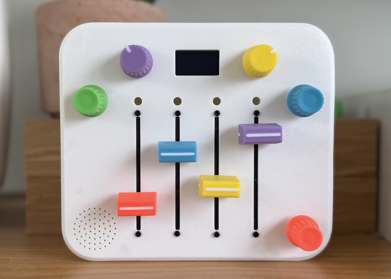
TLDR: I built a portable step-sequencer synthesizer for my daughter’s third birthday. It has four sliders that control four notes in a looping sequence. Slide up = higher pitch, slide down = lower.
It includes:
- An onboard synth module + speaker
- Tempo, volume, scale, pitch, and instrument controls
- An OLED screen with visual feedback + a dancing panda
- A custom PCB and 3D-printed enclosure
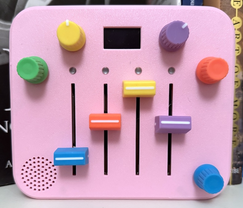
It's a child-friendly, tactile music toy. Here's the pink edition in action:
Why I built this
My daughter received a Montessori activity board full of switches and LEDs for her first birthday. Watching her twist knobs and flip the switches reminded me of the control surface of a synth, and I wondered if I could build a musical version - something simple, tactile, and creative that didn’t require holding down buttons to keep the sound going. A year later I finally decided to build it. I had no prior hardware experience, so this became an excuse to learn about microcontrollers, CAD, PCB design, and 3D printing.
First steps
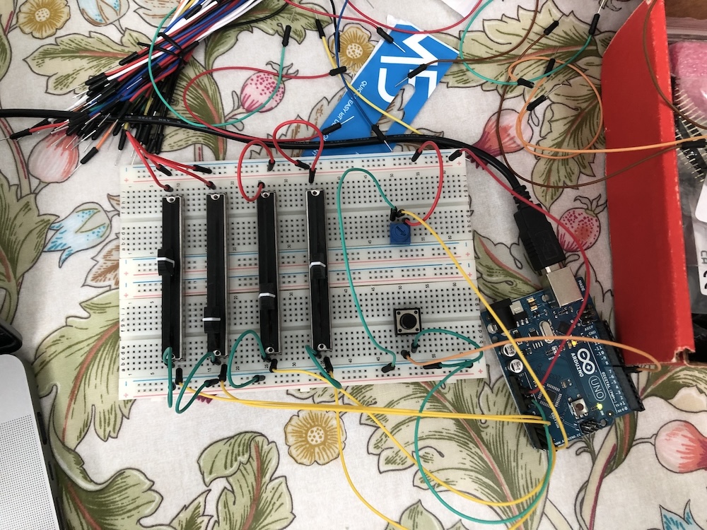
I started the project with a 15 year old Arduino Inventors Kit and only a vague idea about how to use it. The first goal was simple: build a basic MIDI controller on a breadboard. If I could get some potentiometer readings, map them to 12 discrete values - one for each note in an octave - and emit MIDI messages, I would have taken a small step in the right direction. Adding an onboard synth module and designing a pretty box to put it in could wait until later.
Reading the potentiometer inputs and turning them into the MIDI messages using the Arduino MIDI library was easy enough. To hear the output, I wrote a small Python script that intercepted the MIDI messages and forwarded them to my Mac’s default MIDI device, which Logic Pro could pick up. That let me “play” the breadboard through software instruments.
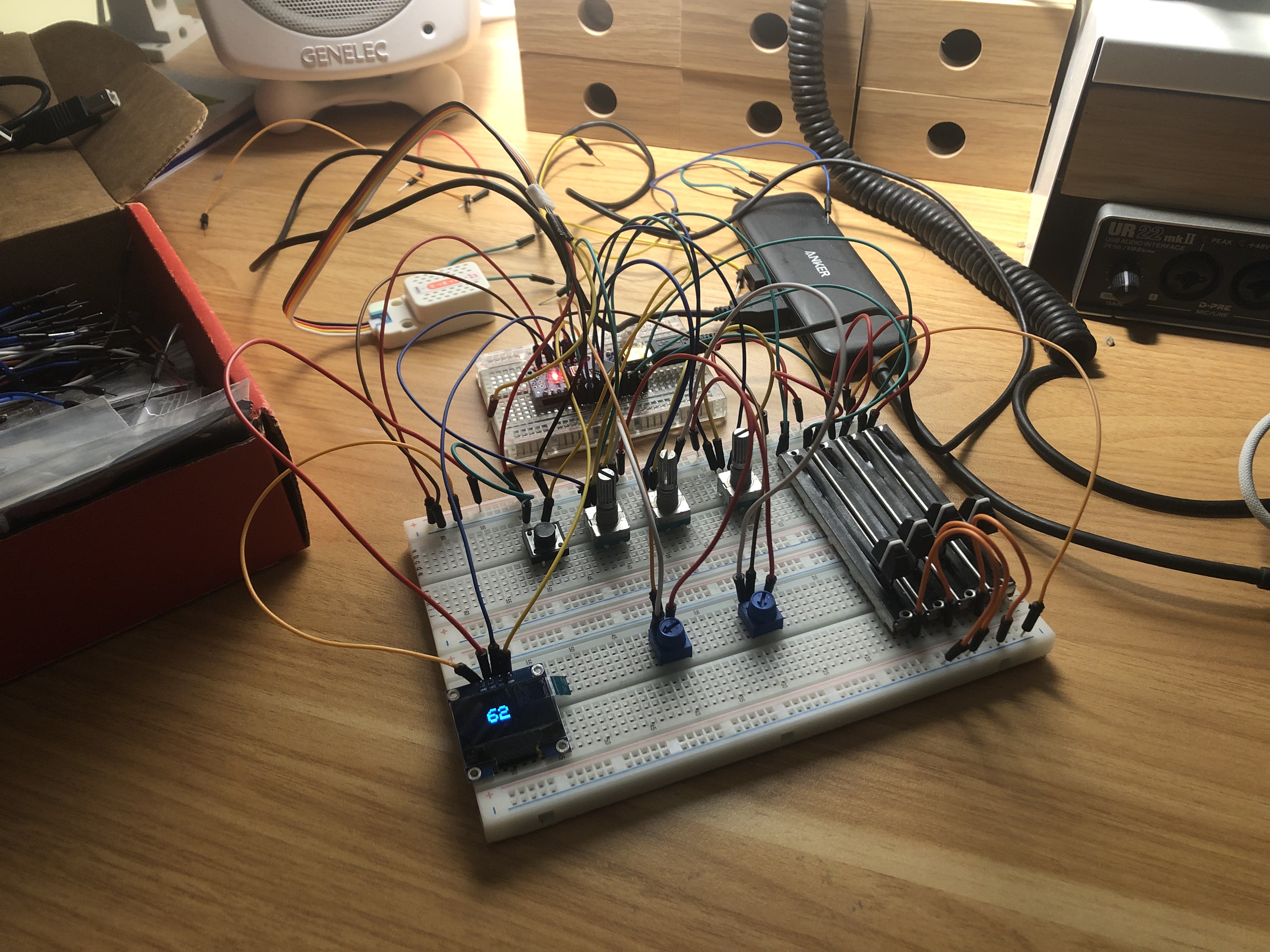
Once I had the hang of wiring up potentiometers and rotary encoders, the next step was to move the audio synthesis from Logic to my breadboard. For this I used a little $12.95 SAM2695 synthesiser module with an integrated amplifier and speaker. Its inner workings remain a mystery to me but it does what I need it to and I was happy reduce the amount of time to get a functioning prototype into my daughter’s hands. I also moved to an Elegoo Nano here due to its low cost and increased number of analog pins.
Next, I added small OLED screen to provide some visual feedback and character and used the handy u8g2 graphics library. This was trickier than I expected: the Nano has so little RAM that I couldn’t buffer a full frame. I had to update the screen in small patches, and large updates were slow enough that they occasionally interfered with encoder reads, and caused laggy notes at faster tempos. I’ve still got some work to do to iron out blocking screen updates, but for now I pushed through and accepted a bit of lag. I added a little dancing panda that I adapted from one I found in a pixel art tutorial which I can no longer find - if you’re the original creator, please let me know so I can credit you!
For developing on-the-go, I discovered the Wokwimicrocontroller simulator. It let me build a virtual schematic and test code without luggin around the my fragile prototype. They have a free online simulator and a paid VS Code plugin that lets you create your diagrams in the IDE.
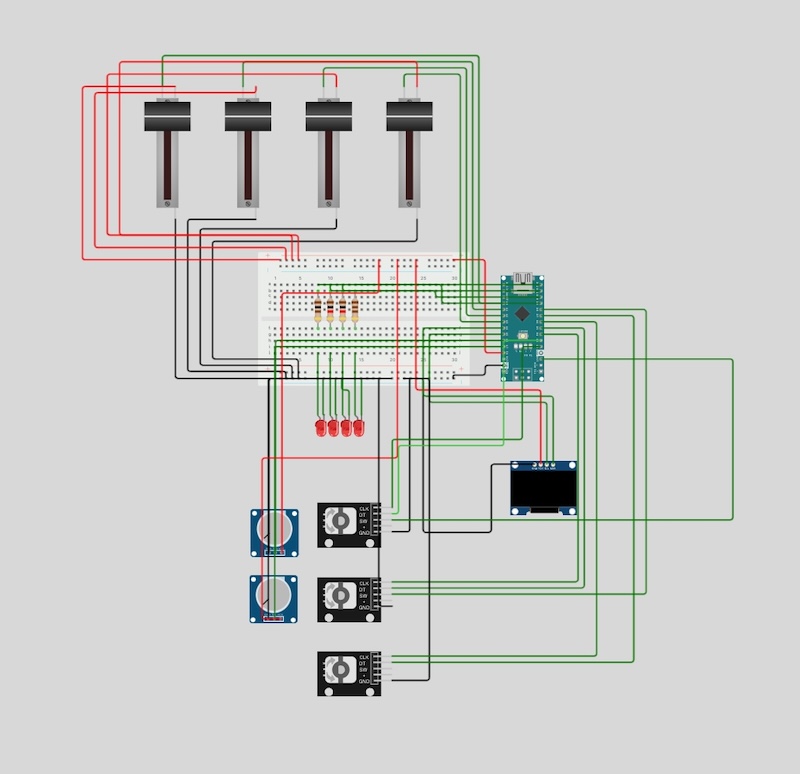
The circuit drawn in Wokwi
Once I had a functional circuit it was time to move on to designing an enclosure and assembling a complete version of the synthesiser that my daughter could play with.
Adventures in CAD
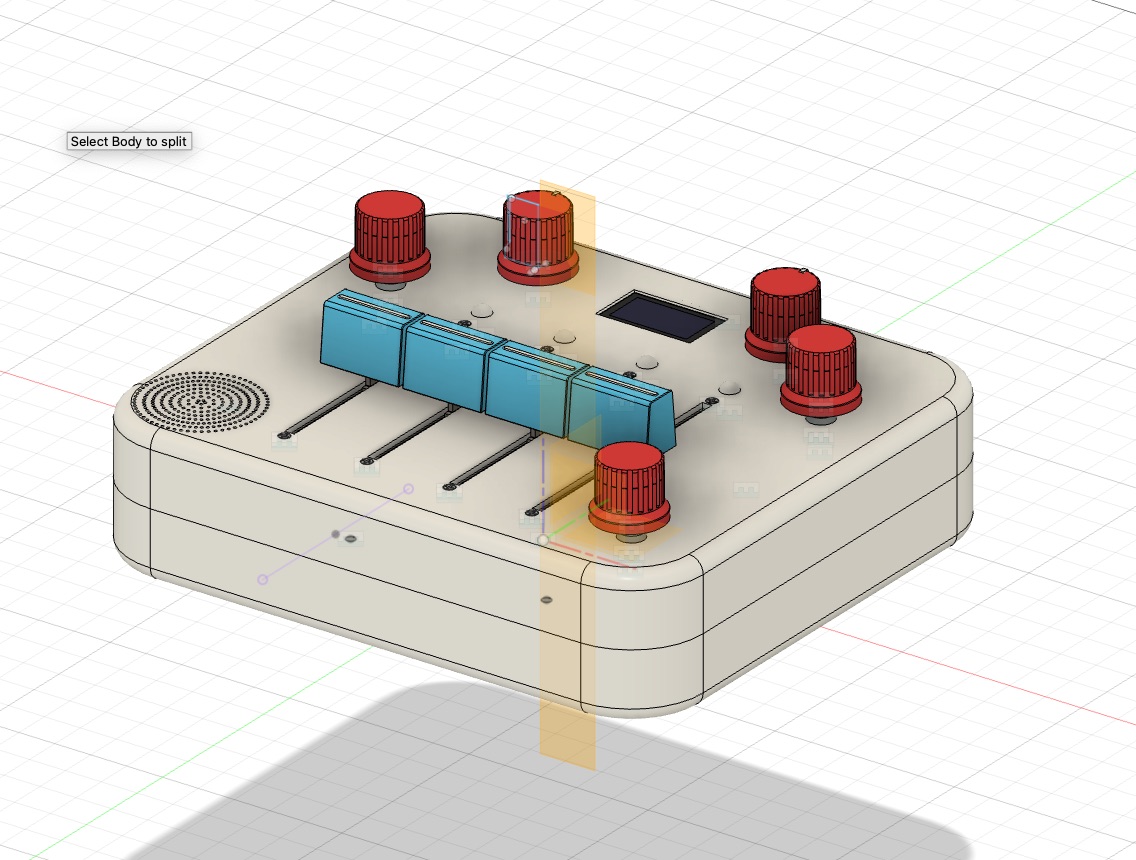
After wiring up the breadboard, the next hurdle was figuring out how to build a proper enclosure. I looked for off-the-shelf cases, but nothing matched the size I needed, and everything seemed to come in either black or beige. So I decided to learn some basic CAD and 3D-print the enclosure on a friend’s Bambu Labs A1 Mini.
I downloaded Fusion 360 and started following tutorials. With only an hour or two to spare in the evenings, progress was slow at first. I’d never used any CAD software before, so I was constantly switching between learning the software and trying to make actual progress on the design. For other beginners, I highly recommend Product Design Online’s Learn Fusion 360 in 30 Days and this excellent video by wermy.
After a few weeks of trial-and-error, I finally had a design I could print:

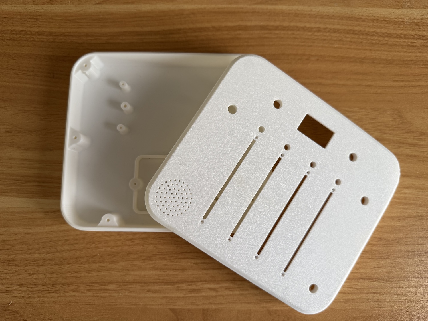
Thank you Tom for printing these! A year's supply of filament coming your way.
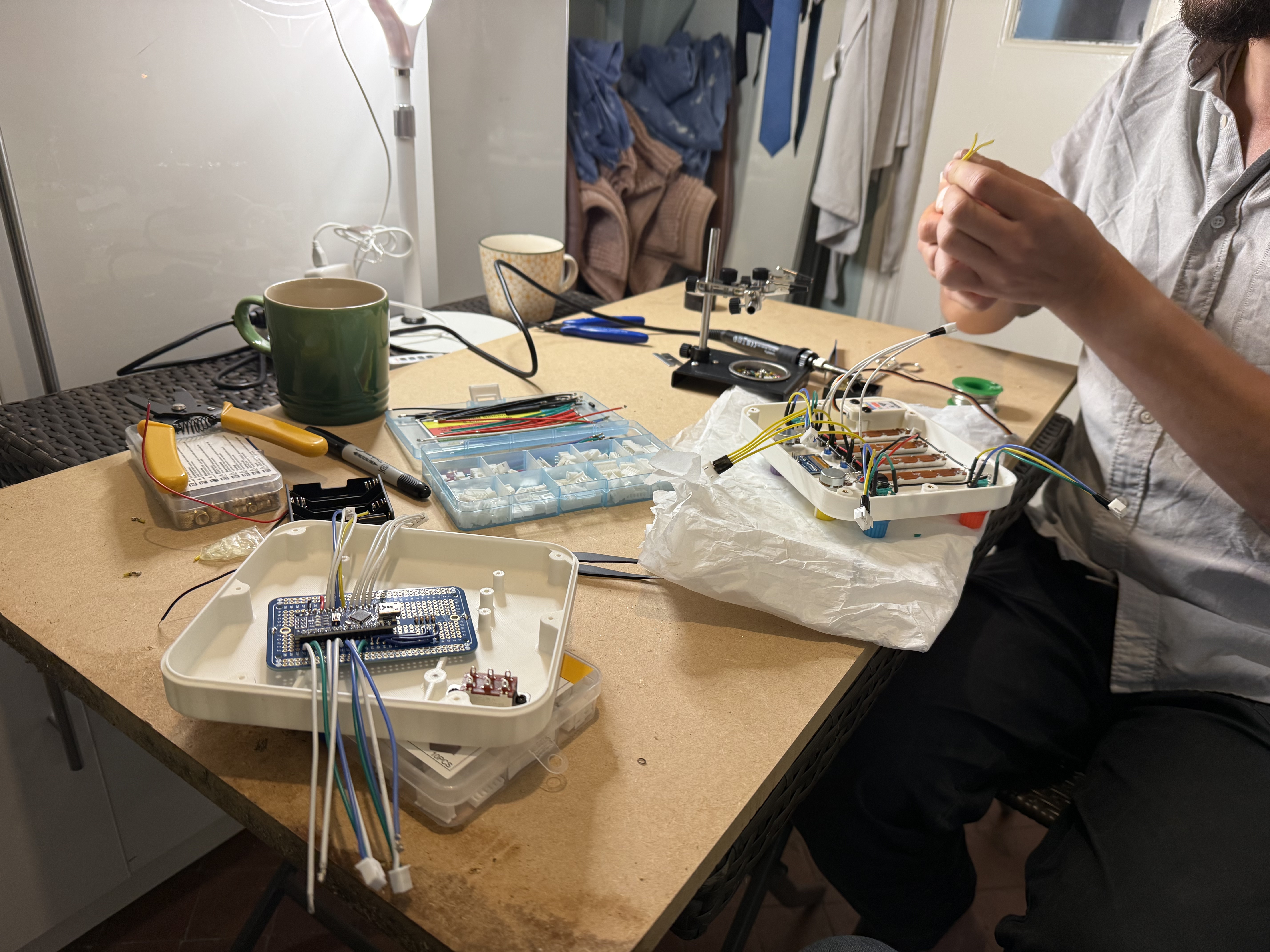
First assembly
Moving the circuit to a proper PCB felt daunting, so for the first version I hand-wired everything on a solderable breadboard. The good: hanging out and drinking some wine with my friend, who kindly offered to help with the soldering. The bad: when the time finally came to close the two halves of the enclosure, stuffing the rats nest of wires inside ended up putting pressure on a bunch of the delicate soldered joints and breaking them. My daughter could play around a bit with it - enough for me to convince myself that she’d genuinely enjoy using it - but it was fragile. I also wanted to make a few units for friends, which meant I needed something more robust and faster to assemble. Time to design a PCB.
Romain, I definitely owe you a bottle or two...
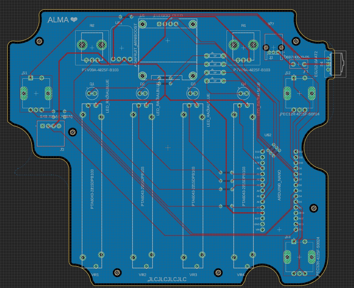
Designing a PCB
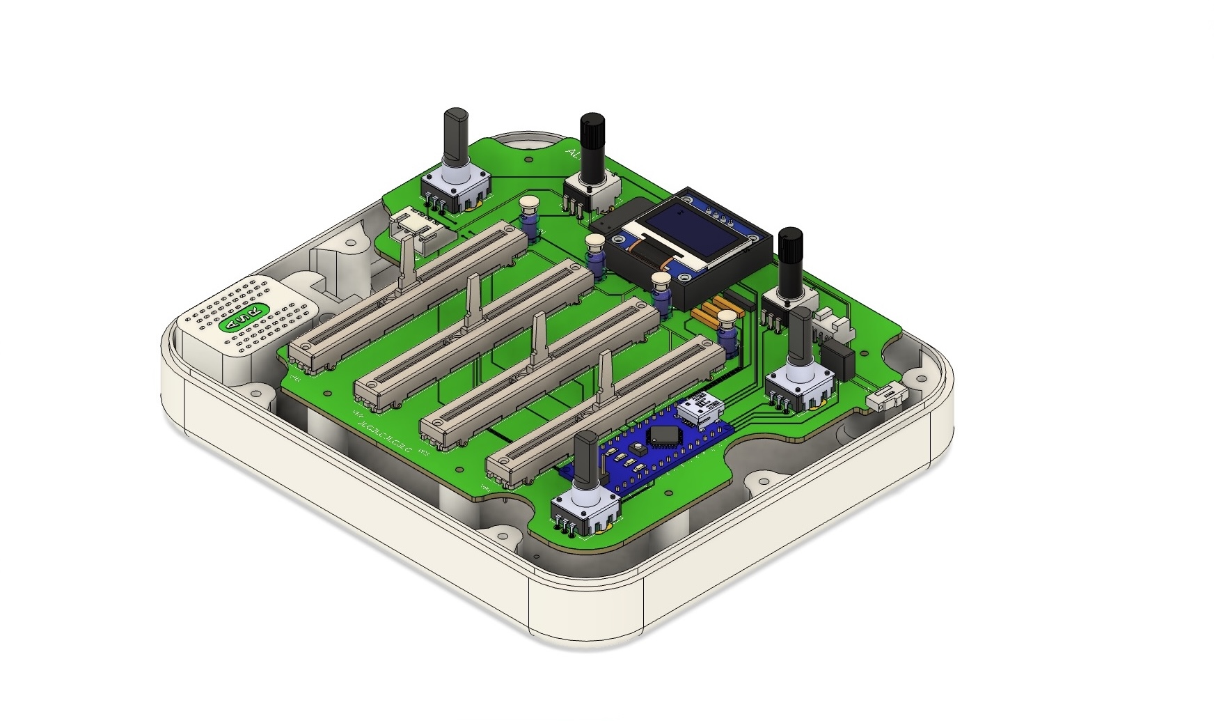
Once again I was back on YouTube and fumbling my way through an unfamiliar workflow, though I stuck with Fusion 360 which has its own electronics design suite. For my first attempt I decided that I’d focus on surface-mounting the various components and save integrating the microcontroller into the board for a future project. A large chunk of the time here was spent reading datasheets, sourcing parts and importing their footprints/models into Fusion 360. Once I had learned the basics, I was able to route the circuit on a 2-layer board. One of the nice things about Fusion is that you get a full 3D model of the assembled PCB, which makes designing the enclosure much easier.
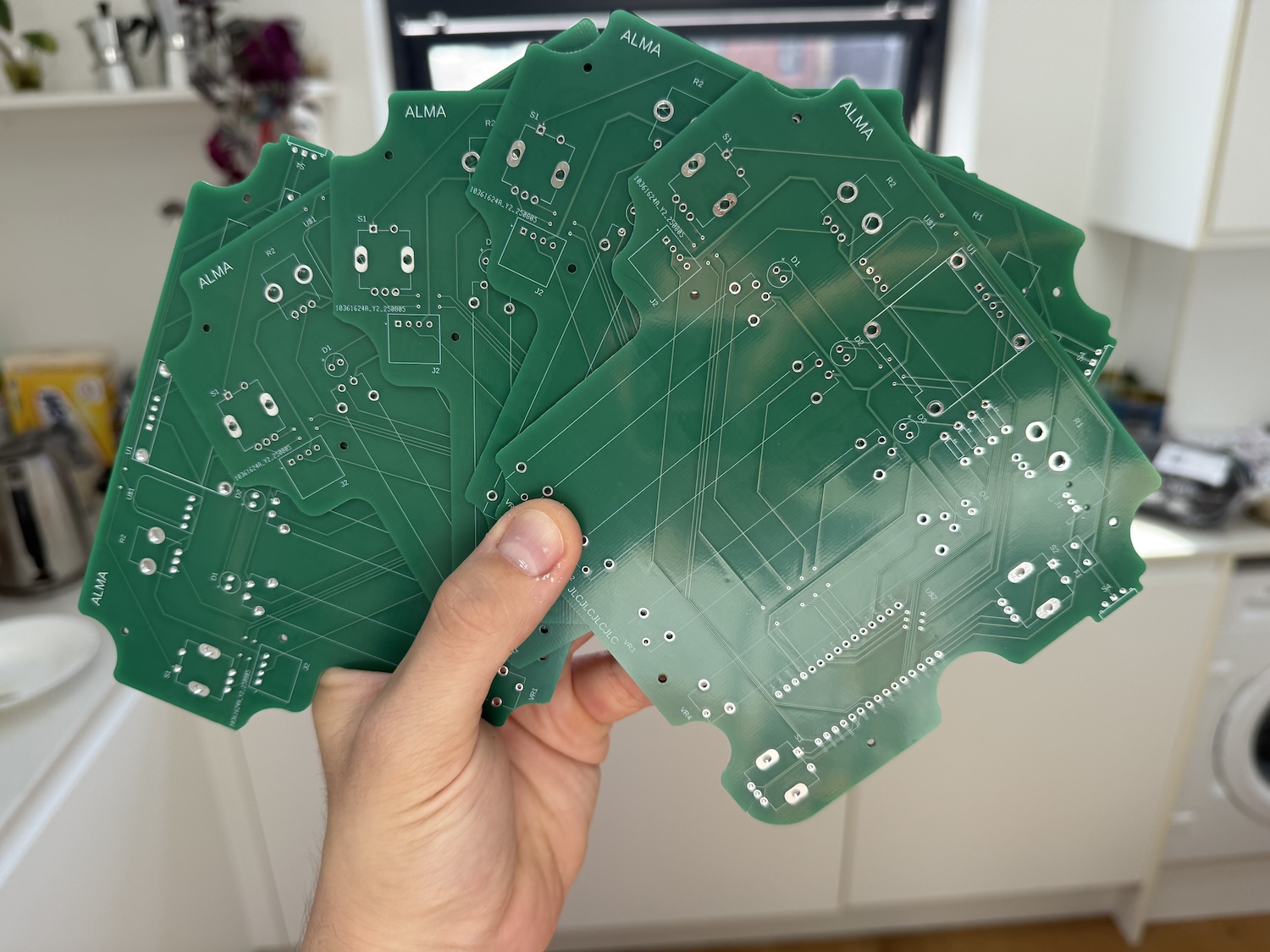
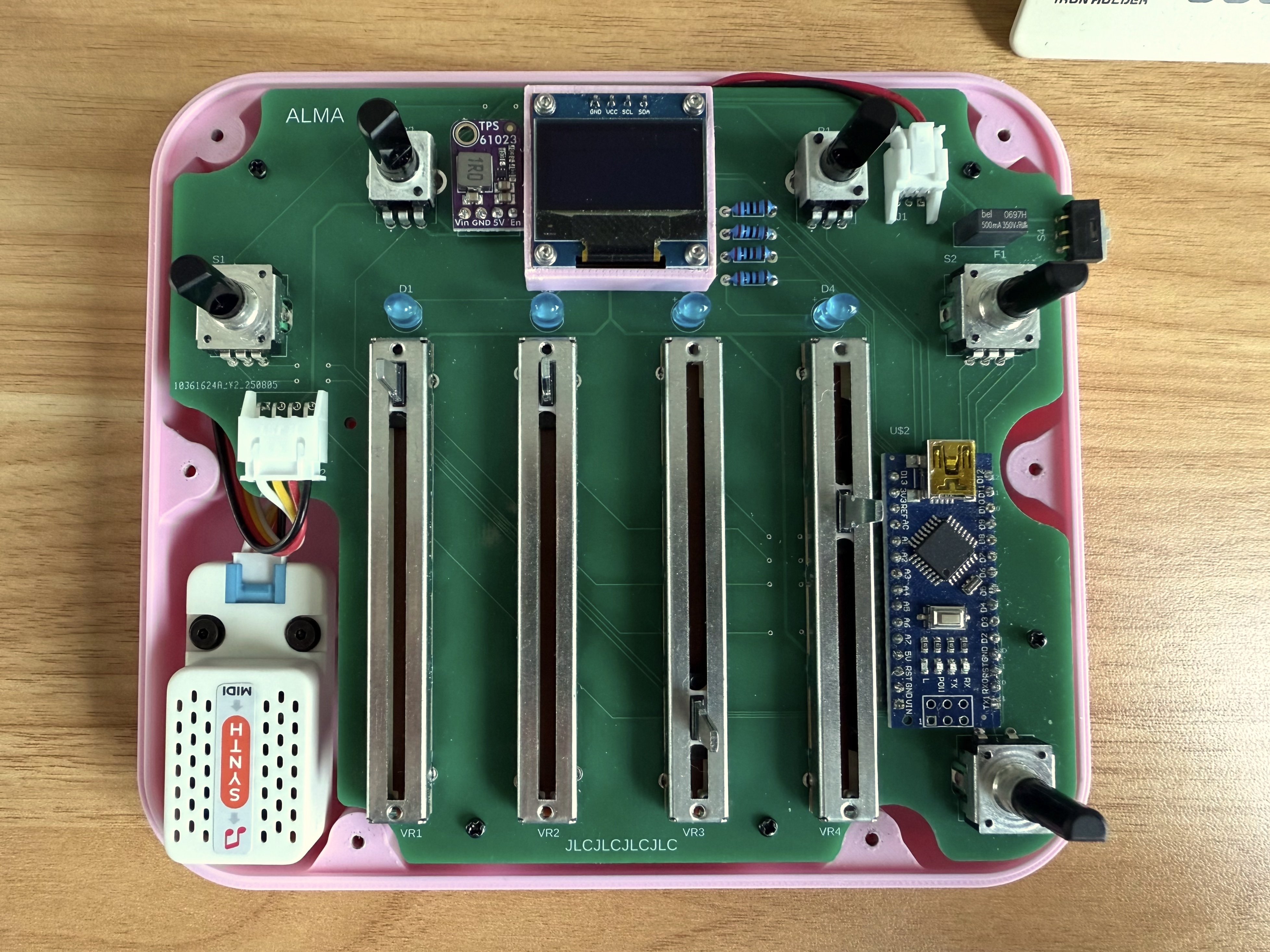
When I was finished, I exported the PCB design file and uploaded it to JLCPCB. Five boards (the minimum order) cost £35.41 including shipping, and they arrived five days later. It blows my mind that this is possible.
The path to power
For my first version I had decided to use 4 AA batteries and use the Arduino’s built-in voltage converter to provide a steady 5 volts. Something I overlooked, however, is that the Arduino’s VIN pin that provides a regulated 5V to the board requires 7-12V input, while my batteries will provide, at best, 6V when new. The board seemed to work OK at this voltage but it would be vulnerable to random resets as the voltage starts to sag and a short battery life.
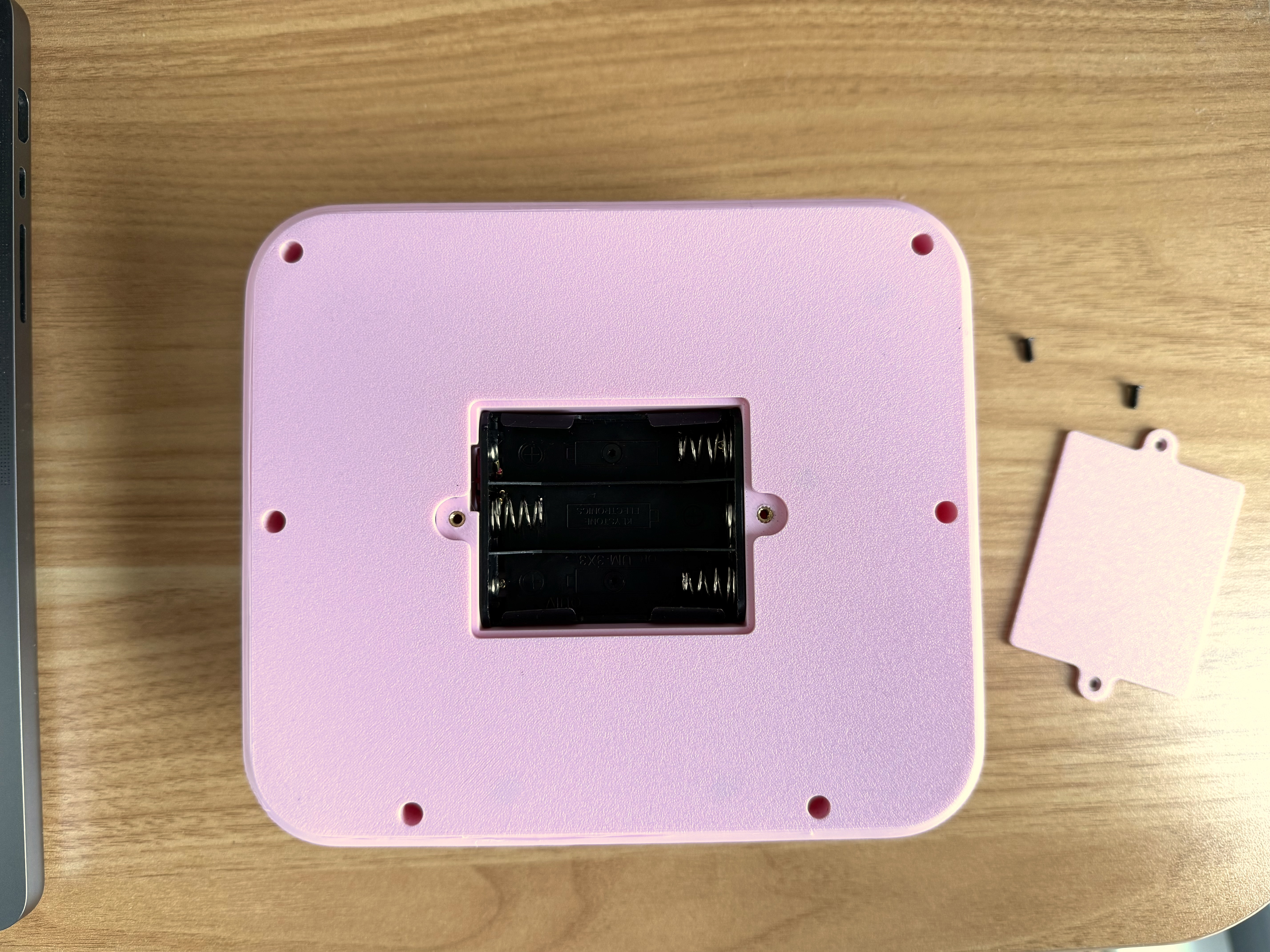
For the next iteration I decided to get rid of one of the batteries and introduce an Adafruit Miniboost to provide a regulated 5V power supply to the Arduino from the combine 4.5V from the three AA batteries. This allowed me to reduce the weight a little bit and provide the synth with a stable supply of power for a longer duration.
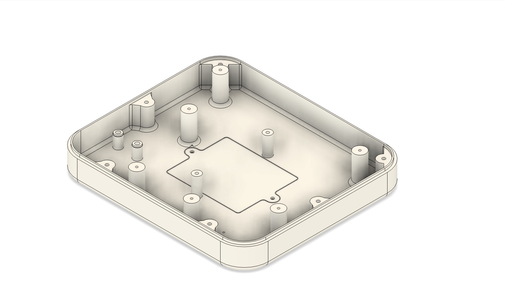
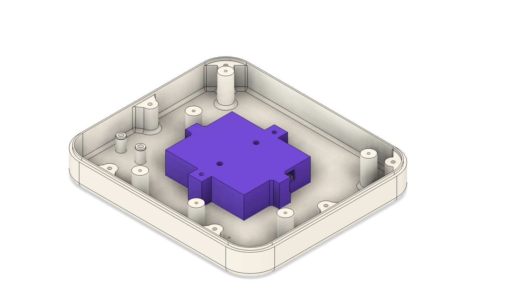
The final version
Finally, I updated the enclosure so that I could securely attach the PCB and added a neat little battery compartment. I also added a small bezel to raise the height of OLED display.

Reflections & next steps
It’s been just over a week since my daughter unwrapped her new synth. It now lives on the shelf with her other toys, and so far it gets regular use and is holding up well. One of my goals was to make something fun to fiddle with at a superficial level, but with enough depth to stay interesting as she gets older. The first part seems true, and I’ll see how the second plays out over the coming months. There are still a few kinks to iron out, such as the lag when updating the screen. I’m also planning to upgrade the Elegoo Nano to an ESP32, which should simplify the firmware and open up more options for fun display graphics.
After watching a few children and adults (musical and non-musical) play with it, I think there might be the germ of a real product here. With a better synth engine, audio outputs, and a way to chain multiple units together, it could be a playful introduction to electronic music for older kids - maybe even adults. However, adding features is one thing, but actually bringing a product to market is another. The challenges aren’t just technical: they’re regulatory and financial. Safety certification (UKCA/CE, and FCC in the US) can cost £5-10K or more. Manufacturing is another hurdle. A 3D-printed enclosure is fine for a prototype, but a real product likely needs injection-molded parts, which require expensive tooling. Even a small production run would need more upfront capital than I can sensibly invest right now.
For the moment I’m treating it as a learning project, but the response so far has been encouraging. A more polished open-source version for makers, or possibly a small Kickstarter campaign, might be viable next steps. If anyone reading this has experience bringing small-run hardware to market, I’d love to hear from you.

![Stroustrup says subscripts and sizes should be signed [pdf]](https://news.najib.digital/site/assets/img/broken.gif)

