.png)

Introduction
Silicon (Si) with a high theoretical capacity (≈3579 mAh g−1, Li15Si4) at atmospheric temperature has emerged as the most promising negative electrode material to improve the energy density of lithium-ion batteries (LIBs)1,2,3,4. However, the substantial volumetric changes of Si negative electrode (>300%)5,6,7 during lithiation and delithiation cause severe mechanical stress and electrochemical side reactions at the particle, electrode, and cell levels, specifically resulting in particle pulverization for crystalline microparticulate Si due to anisotropic lithiation with preferential expansion along the {110} crystallographic planes8,9,10, loss of electrical contact for the bulk Si film11,12, large amount of solid electrolyte interphase (SEI) formation on the nanostructured Si owing to its large specific surface area13,14,15,16. These detrimental effects are crucial for capacity loss and cycle life, significantly limiting the practical applications of Si negative electrodes17,18. Thus, reducing the volume expansion is the primary concern for the widespread commercialization of Si negative electrodes19. Various buffering strategies, such as porous Si structures20 and yolk-shell architectures21 have been designed. Nevertheless, these reported strategies face a trade-off: enhancing mechanical stability often compromises rate performance and fast-charging capability, while prioritizing electrochemical kinetics can lead to poor cycle life due to insufficient structural integrity22,23.
Previously engineered Si materials for buffering can be broadly classified into three categories based on the contact modes between the buffering architectures and electrolytes, considering both mechanical stability, defined as the design of structures and morphologies that maintain structural integrity, and kinetic, defined as the ion/electron diffusion ability (as shown in Fig. 1): open-pore structures24,25, buried-pore structures26,27 and closed-pore structures28,29. First, open-pore structures offer short lithium ions (Li+) transport paths, thus exhibiting good kinetics. However, these structures have high specific surface areas, exposing the Si surface directly to the electrolyte, which leads to severe side reactions and low initial Coulombic efficiency (ICE)30. Additionally, these structures are prone to collapse during cycling, resulting in further exposure of the Si surface and rapid capacity decay31 (in the fourth quadrant of Fig. 1). Even with surface coating and modification, it is challenging to withstand the stress caused by the deformation of Si negative electrodes32. Second, buried-pore structures incorporate small and closed pores within the Si particles. However, these buried pores are insufficient to fully accommodate the substantial volume expansion of the entire Si particles. Consequently, inadequate buffering capability would lead to structural fluctuations or even collapse, which primarily affects mechanical stability. Additionally, the longer charge transport pathways across the thick buffering framework contribute to unsatisfactory transport kinetics26,27 (in the third quadrant of Fig. 1). Third, closed-pore structures including typical yolk-shell structure33 and pomegranate-like structure34 could ensure structural integrity through the outer protective shell and sufficient reserved voids when the Si core undergoes volume changes or particle cracking upon lithiation and de-lithiation. This design demonstrates reduced volume expansion35. However, the diffusion of Li+ is significantly impeded at both the coating interface and the voids between Si and the electrolyte. Consequently, this structure exhibits undesired kinetics despite its mechanical stability (in the second quadrant of Fig. 1). Hitherto, structures integrating both high mechanical stability and desirable electrochemical kinetics have been rarely reported. In addition, the above three structures usually involve complicated procedures to build exquisite pores, plaguing their practicability for scalable fabrications. The ideal Si negative electrode, combining high capacity, minimal expansion, long lifespan, and fast charging, has yet been realized36,37.
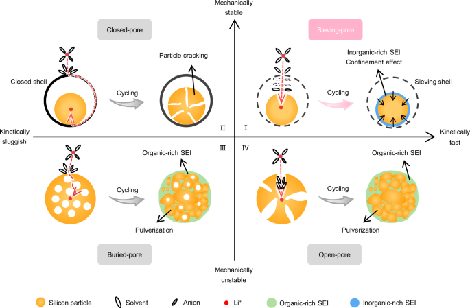
I Sieving-pore structures, due to size sieving effects at the pore entrance, allow Li+ and anions with partial solvents to enter the pores and participate in electrochemical reactions, thereby effectively suppressing side reactions and favoring the formation of inorganic-rich SEI within the pores. Meanwhile, Li+ can move smoothly through the pore entrance, and the resulting inorganic-rich SEI facilitates rapid Li+ conduction and mechanical confinement for the expansion of Si in pores, demonstrating mechanical stability and fast kinetics. II Closed-pore structures, in which the expanded/cracked Si core is protected by the closed shell, while the ion transport paths are blocked, deliver mechanical stability but sluggish kinetics. III Buried-pore structures, in which the Si surface is directly exposed to the electrolyte, and the structure tends to collapse during cycling, result in mechanical instability and long Li+ diffusion distances. IV Open-pore structures, in which the Si surface is directly exposed to the electrolyte, and porous structures shorten ion diffusion paths, yet the structure easily collapses during cycling, lead to mechanical instability but fast kinetics.
Herein, we present a design rationale that fundamentally integrates mechanical stability and fast kinetics for realizing significantly improved cycling and rate performance in practical low-expansion Si negative electrodes (in the first quadrant of Fig. 1). This rationale is embodied in a sieving-pore structure, featuring a carbon nanopore body with reserved voids to buffer Si expansion and a carbon sub-nanopore entrance sieving ions from most solvents. The sieving effect, arising from the precisely engineered sub-nanometer pore entrance, facilitates rapid ion transport and pre-desolvation, profoundly altering the in-pore solvation environment and forming a robust inorganic-rich SEI. Furthermore, we find a stress-voltage coupling effect, wherein the mechanical confinement from the inorganic-rich SEI layer and the carbon supports effectively prevents the formation of crystalline Li15Si4 (c-Li15Si4), a critical improvement in mitigating the issue of significant phase transformation stress and parasitic reaction. The sieving-pore silicon/carbon (SSC) composite negative electrodes demonstrate stable cycling performance (200 cycles with a capacity retention of over 97% and a capacity fade ratio as low as 0.015% per cycle), together with high ICE (93.6%) and low electrode swelling (58% at 4 mAh cm−2 in the fully lithiated state). Benefiting from the improved kinetics, good rate performance (750 mAh g−1 at 6 A g−1) is obtained. Moreover, the assembled Ah-level pouch cell shows stable cycling performance (80% capacity retention for 1700 cycles at 2 A) and high-rate performance (10-minute fast charging). Additionally, the SSC can be fabricated on a large scale, demonstrating practicability in terms of cost, fabrication, and performance in Si negative electrodes (Supplementary Note 1).
Results
Synthesis and characterization of the SSC materials
The SSC materials were prepared through a two-step chemical vapor deposition (CVD) process. First, Si was synthesized by the thermal decomposition of silane (SiH4) gas at 450 °C on porous carbons (PCs). This process led to the embedding of amorphous Si along the micropore walls of the PCs, resulting in the formation of a Si/C (SC) negative electrode with an open-pore structure38,39. Subsequently, acetylene (C2H2) gas was thermally decomposed at 600 °C to deposit sieving carbon onto the SC, effectively narrowing the pore entrances and forming the sieving-pore structure40 (Fig. 2a). Additionally, since the pyrolysis of C2H2 is a diffusion-controlled process, the deposition of C2H2 involves gradual gas diffusion from the pore entrance to the pore body. As a result, the rapid pyrolysis of C2H2 at 600 °C tends to occur at the pore entrances rather than the pore body, ultimately forming sieving-pore structures. Notably, the pore size distribution of PCs is crucial for the pyrolysis behavior of SiH4 and C2H2. CVD technology faces challenges in tightening the entrance size of mesopores and macropores to a sieving-pore structure due to the small molecular kinetic diameters of SiH4 and C2H2, while ultra-micropores (<1 nm) are easily fully occupied by the pyrolyzed Si or sealed by the deposited carbon, rendering them incapability of buffering or sieving (Fig. 2a). Therefore, the used PCs in this work were customized by pre-coating them with a layer of carbon to adjust the pore size distribution for better compatibility with Si and carbon deposition40. This SSC material can be fabricated on a large scale with an abundant source material supply and simple CVD technology (Supplementary Note 1). Supplementary Fig. 1 shows the 20 kg product of SSC materials per batch, demonstrating the potential for fabrication scalability and reproducibility in terms of material properties to electrochemical performance (Supplementary Note 2).
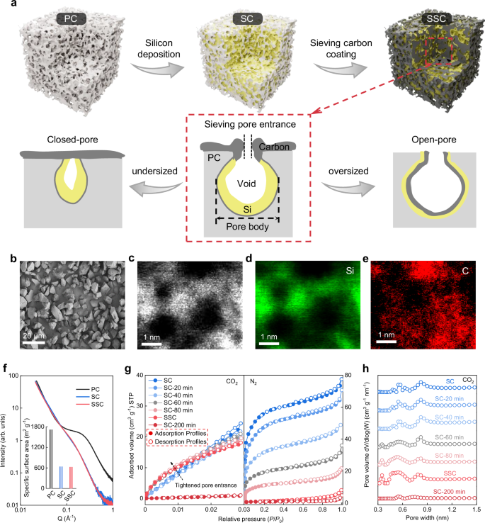
a Schematic of the synthetic procedure of SSC materials and the comparisons between the customized-micropore, undersized-pore, and oversized-pore PC supports for fabricating sieving pores. The PC support is illustrated as a grey pore, while the yellow and black irregular shapes represent the deposited Si layers and carbon layers, respectively. b SEM images of SSC particles. c–e Spherical aberration-corrected HAADF-STEM and corresponding EDS mapping of SSC samples. f SAXS curves of PC, SC, and SSC samples. Inset: the calculated SSA of these three samples. g N2 (77 K) and CO2 (273 K) adsorption-desorption isotherms of SC, SC with different C2H2 deposition times, and SSC samples. h Pore size distributions derived from CO2 adsorption-desorption isotherms, based on the non-local density functional theory (NLDFT) model, for SC, SC samples with different C2H2 deposition times, and SSC samples.
After the deposition of Si and carbon, the morphology of SSC particles shows no significant difference compared to the pristine PC and SC particles (Fig. 2b and Supplementary Fig. 2). The particle size distributions of these three materials are essentially the same, with the D50 values of 7.12 μm (PC), 7.26 μm (SC) and 7.35 μm (SSC) (Supplementary Fig. 3). The tap densities of PC, SC, and SSC samples are 0.42, 0.66, and 0.88 g cm−3, respectively, as shown in Supplementary Fig. 3. The mass content of Si in SSC is calculated to be 49 wt.% (the detailed calculations were presented in Supplementary Note 3). It is noted that a further increased Si content leads to rapid decay in capacity retention (Supplementary Note 4). Comprehensively considering the high Si mass content, the unchanged particle size distributions, and the greatly increased tap density from PC to SSC, it can be deduced that the deposited Si is not located on the outer surface of the carbon support. The X-ray diffraction (XRD) patterns (Supplementary Fig. 4a) show no obvious characteristic diffraction peaks of crystalline Si, proving the deposited Si inside the pore is amorphous. As shown in Raman spectra (Supplementary Fig. 4b), the appearance of a new peak at 468 cm−1 in the SC and SSC samples also supports the amorphous state of the deposited Si41. Additionally, the high-resolution transmission electron microscopy (TEM) images exhibit the amorphous property of Si and a uniform distribution of Si and C at lower magnification (Supplementary Fig. 5). As shown in Supplementary Fig. 6, energy dispersive X-ray spectroscopy (EDS) mapping of Si and C for SSC at higher magnification reveals a uniform and continuous distribution of the C element, while the Si element exhibits a tree-branch-like distribution, corresponding to the white regions in the dark-field TEM image. These TEM results further confirm the presence of Si in the pores, with Si distributions resembling the nanopore distributions in the original PCs. As illustrated in the spherical aberration-corrected high-angle annular dark-field scanning transmission electron microscopy (HAADF-STEM) image and the EDS mapping of the SSC sample (Fig. 2c–e), the Si element distribution is enclosed by the carbon element, indicating that the deposited Si nanoparticles are confined within the carbon.
To further illustrate the distribution of Si, a 900 °C annealing process was applied to convert the Si into silicon carbide (SiC) (Supplementary Fig. 7a)38. To some extent, the distribution of SiC within the carbon supports reflects the original location of the amorphous Si. To visualize the SiC distribution, focused ion beam (FIB) sectioning was employed to slice individual particles, allowing for a clear view of the internal SiC distribution in the SSC particle. As shown in Supplementary Fig. 7b, the SiC appears as individual nanoparticles embedded within the micropores of the carbon support. Figure 2f shows the small-angle X-ray scattering (SAXS) curves of PC, SC, and SSC samples, where the signals in the intermediate Q range represent carbon porosity42. A significant decrease in porosity is observed from PC to SC, indicating that the Si deposited into the nanopores of the PCs reduces porosity. Notably, there is no discernible difference between the SC and SSC samples, suggesting that the deposited carbon tends to accumulate at the pore entrances, tightening their entrance size rather than filling the pores themselves. The calculated specific surface area (SSA) from SAXS has a large decrease from PC to SC and a very minor decrease from SC to SSC. This indicates that the deposition of SiH4 inside the pores, while the deposition of C2H2 predominantly takes place outside the pores. Consequently, the interior void space is still retained after the carbon deposition, which tightens the pore entrance.
To further characterize the sieving structure of SSC samples with sub-nanometer pore entrances, the nitrogen (N2) and carbon dioxide (CO2) adsorption-desorption measurements were conducted. In Fig. 2g and Supplementary Fig. 8a, the N2 adsorption-desorption isotherms of PC and SC samples appear as type I shape, indicating a typical microporous structure. The customized PC has a large N2 adsorption volume of 0.85 cm3 g−1 and its SSA, calculated using the Brunauer-Emmett-Teller (BET) method, is 1678 m2 g−1. After the thermal decomposition of SiH4, the N2 adsorption volume of the SC decreases significantly to 0.12 cm3 g−1, and the SSA drops to a low 201 m2 g−1, further confirming that Si is deposited inside the nanopores of PCs. Considering CO2 diffuses more rapidly at 273 K compared to N2 at 77 K, CO2 adsorption-desorption isotherms at 273 K were used to analyze the ultra-micropores of the samples43. A similar phenomenon is observed in the CO2 adsorption of SC (Fig. 2g and Supplementary Fig. 8b). It is implied that deposited Si particles fill the nanopores of carbon supports, while the remaining micropore adsorption in SC is due to smaller micropores that are too small to allow SiH4 to enter and transform into Si.
By precisely controlling the deposition time of C2H2, we can finely tune the sub-nanometer pore entrance size, as shown in Fig. 2h and Supplementary Fig. 8c. It is evident that as the C2H2 deposition time increases, the pore entrance size of the SC materials progressively decreases, which is accompanied by a corresponding reduction in the N2 adsorption volume. However, due to the smaller molecular dynamic size and enhanced diffusion capability of CO2 at 273 K (the N2 is 0.5 nm at 77 K while the CO2 is 0.35 nm at 273 K)44, the adsorption volume of CO2 does not show a significant decrease. While the SSA of SSC under N2 testing conditions approaches 4.25 m2 g−1, its SSA under CO2 testing conditions still approaches 279.5 m2 g−1 (calculated using the BET method and summarized in Supplementary Table 1 and Supplementary Table 2). Therefore, the pore entrance size of the sieving pores in SSC is in the exact range of 0.35–0.5 nm, where the N2 is not permitted to enter, while the CO2 can penetrate through this narrow pore entrance40,45,46,47,48. In addition, in Fig. 2g, when the deposition time ranges from 20 to 80 min, both N2 and CO2 adsorption-desorption measurements show substantial adsorption, indicating that the pore entrance size is primarily above 0.5 nm, corresponding to an open-pore structure that cannot effectively sieve the electrolyte. When the deposition time is extended to 200 min, neither N₂ nor CO₂ measurements show effective adsorption, indicating that the pore entrance size is primarily below 0.35 nm, which corresponds to the formation of a closed-pore structure. It is noteworthy that these remaining small pores can serve as buffering spaces to accommodate the volume expansion of Si during lithiation (Supplementary Note 5). Additionally, the deposited carbons in SSC do not fully coat and seal the pore entrance, as proven by the Raman spectra with smaller graphene aromatic sheets in SSC compared to the CVD pyrolytic carbons40 (Supplementary Note 6). As discussed in Supplementary Note 7, the specific capacity shows a slight decrease as the pore entrance decreases, but there is a significant improvement in the ICE for the SSC negative electrode, indicating an optimal pore entrance size ranging from 0.35 to 0.5 nm. These results demonstrate that the sieving-pore structure of the SSC material features a pore body with residual void space to buffer the volume expansion of deposited Si during lithiation, and a small pore entrance (0.35–0.5 nm) to efficiently sieve the electrolyte penetration.
Sieving effect for mediated SEIs and kinetics
Ex-situ SAXS testing can be used to characterize changes in the microporous structure of PC, SC, and SSC negative electrodes before and after cycling, which are caused by the growth of SEI within the pores. As shown in Fig. 3a, b, the intensities in the intermediate Q range of the PC and SC negative electrodes after cycling have significantly changed, which is attributed to the excessive growth of irreversible SEI within their differently sized open-pore spaces. Combined with X-ray photoelectron spectroscopy (XPS) analysis (Fig. 3d and f), these SEIs are primarily composed of organics and are distributed on the particle surface and within the pores, which is detrimental to the subsequent cycling and fast charging of the negative electrode49,50,51. In contrast, Fig. 3c shows that the microporous structure of the SSC negative electrodes undergoes minimal changes after cycling. Based on XPS analysis (Fig. 3d and g), the filling of these micropores is due to the formation of inorganic-rich SEI components. The difference in the spatial distributions and compositions of the SEI in the cycled SC and SSC negative electrodes was investigated to highlight the impact of the sieving-pore structure on interfacial electrochemistry. The XPS depth profile illustrates the composition of the SEI within the SC and SSC negative electrodes. As the etching depth increases, signals and contents of Si-Si gradually stabilize, reflecting the internal active Si components of SSC particles (Supplementary Fig. 9). As shown in Fig. 3e, a significant amount of inorganic-rich SEI components exists within the SSC particles, with proportions of lithium fluoride (LiF) reaching 65.7% (much higher than that of SC about 30.6%, both without excluding the detected carbon signal derived from Si/C). Based on the information provided by the XPS spectra in Fig. 3f, g, we depict the distribution of SEI components, highlighting the presence of inorganic-rich SEI inside the pores of the SSC as specifically shown in the illustration (inset image in Fig. 3c). This type of sub-nanometer pore entrances, combined with inner inorganic-rich SEI, could provide a fast diffusion pathway for Li+ to enter and access the Si inside the pores. In comparison, the inorganic components are much less in the pores of SC negative electrodes (inset image in Fig. 3b), which is detrimental to the ICE and transport kinetics. To further demonstrate the existence of an inorganic-rich SEI within the sieving pores of the SSC negative electrodes, SSC negative electrodes after 20 cycles were prepared by FIB sectioning, followed by HRTEM and electron energy loss spectroscopy (EELS) spectrum imaging. As illustrated in Supplementary Fig. 10, the prominent peak at 61.6 eV, accompanied by a smaller bump at 65.6 eV, represents the characteristic fingerprint of LiF in the SEI layer, while the signal from 98.8 eV to 120 eV is a characteristic feature of Si52,53. Notably, the simultaneous detection of EELS signals of Si and LiF confirms the formation of an inorganic LiF SEI layer on the Si surface within the pores.
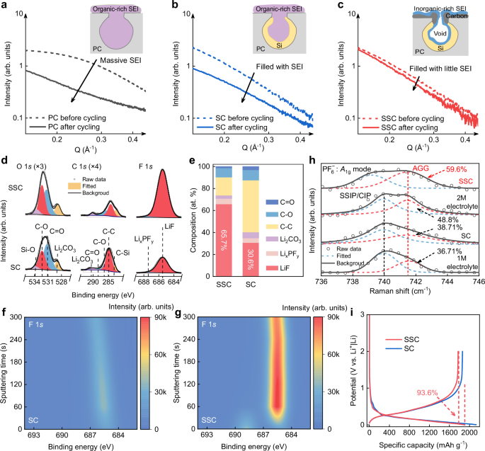
a–c SAXS patterns of PC (a), SC (b), and SSC (c) negative electrodes before (dashed line) and after five full cycles at de-lithiated state. The cells were cycled at a specific current of 0.075 A g−1 for the first two cycles and 0.75 A g−1 for the subsequent three cycles at ambient temperature. Inset: SEI distribution within nanopores. The inorganic-rich SEI and organic-rich SEI are blue and purple irregular shapes inside, respectively. PC support is illustrated as a grey pore, while the yellow and black irregular shapes represent the deposited Si layers and the sieving carbon layers, respectively. d XPS characterization of SSC and SC negative electrodes after 10 cycles with 300 s of Ar+ sputtering. The cells were cycled at a specific current of 0.075 A g−1 for the first two cycles and 0.75 A g−1 for the subsequent eight cycles at ambient temperature. e Content of SEI compositions at a sputtering time of 300 s in SC and SSC negative electrodes. The C-C ratio includes some carbon signals derived from porous carbon. f, g Contour maps of F 1 s intensity for SC and SSC negative electrodes under increasing sputtering time. h Raman spectra of electrolytes with different concentrations and the electrolyte configuration in the nanopore of SC and SSC. i The initial charge/discharge profiles of SC and SSC negative electrodes at a specific current of 0.075 A g−1.
The formation mechanism of the inorganic-rich SEI layer is attributed to the sieving effect, where the sub-nanometer (0.35–0.5 nm) pore entrances in SSC are smaller than various solvated cations, forcing these cations to shed weakly coordinated solvent molecules from their outer solvation sheaths, and even some strongly coordinated solvent molecules from their inner solvation sheaths, when subjected to an external electric field54,55,56. Conventional structures, such as open-pore, buried-pore, and closed-pore structures, cannot effectively regulate the electrolyte structure, which contains a significant number of free solvent molecules. This leads to the formation of an organic-rich SEI layer, primarily composed of organic solvent decomposition products. In contrast, SSC negative electrodes with sieving-pore structure promote a pre-desolvation behavior that induces the formation of an inorganic-rich SEI layer. The underlying mechanism has been demonstrated through Raman spectroscopy and nuclear magnetic resonance (NMR) analysis. As shown in Fig. 3h, a characteristic peak near 740 cm−1 is observed, corresponding to the symmetric P-F stretching vibration of \({{\mbox{PF}}}_{6}^{\,-}\) (A1g)57,58. As the concentration increases, the solvation structure transitions from solvent-separated ion pair (SSIP) or contact ion pair to more aggregated (AGG), indicative of a stronger interaction between \({{\mbox{PF}}}_{6}^{\,-}\) and Li⁺59. Notably, Raman spectra of sieving pores in SSC fully in immersed in the 1 M electrolyte exhibit a more pronounced blue shift and a higher peak area (59.6%) for AGG compared to the 2 M electrolyte (48.8%), approaching a saturation state where AGGs predominantly govern the solvation configuration60. Importantly, the broader peak of electrolyte in the SSC negative electrode is attributed to the nanopore confinement effect on the solvation configuration61. The solvation structure within the nanopores is further verified through 7Li NMR spectra (Supplementary Fig. 11). The 1 M liquid electrolyte displays a sharp peak at −0.84 ppm with a narrow peak width referring to the SSIP chemical environment of Li+. In comparison, in the SSC negative electrodes with electrolytes, this NMR signal broadens significantly due to electrolyte confinement within the nanopores62.
Subsequently, the ability of Li+ transport through SEI and the charge transfer impedances were measured by temperature-dependent electrochemical impedance spectroscopy (EIS)63. As shown in Supplementary Fig. 12 and Supplementary Fig. 13, the SC and SSC negative electrodes after 10 cycles were tested from −20 °C to 20 °C with an increment step of 10 °C. The activation energy of Li+ desolvation (Ea ct) for SSC negative electrodes (61.55 kJ mol−1) is lower than that for SC negative electrodes (66.26 kJ mol−1), indicating that the small pore entrance enhances the kinetics of Li+ desolvation. Similarly, the activation energy of Li+ transport through SEI (Ea int) for SSC negative electrodes (34.47 kJ mol−1) is lower than that for SC negative electrodes (37.76 kJ mol−1), suggesting that the inorganic-rich SEI on SSC negative electrodes facilitates smoother Li+ migration across the interface. Additionally, the interfacial transport kinetics between the sieving-pore structure and the fully closed carbon layer were compared. As shown in Supplementary Fig. 14, the sieving-pore structure exhibits lower Ea int (65.72 kJ mol−1) and Ea ct (56.67 kJ mol−1) compared to Ea int (66.5 kJ mol−1) and Ea ct (91.45 kJ mol−1) of the fully closed-pore carbon layer. The above results strongly confirm the significant advantage of sieving pores and the inner inorganic-rich SEI pathway in SSC negative electrodes for interfacial Li+ kinetics, compared to the usual closed-pore carbon coating structure for Si negative electrodes.
The ICE and cyclic Coulombic efficiency (CE) were employed to assess the stability of the interface. Figure 3i shows the discharging-charging curve of SC and SSC negative electrodes, revealing an ICE of 93.6% followed by a rapid rise in CE (> 99.5% after 4 cycles, with an average CE of 99.9% from 50th to 100th cycles) during extended cycling (Supplementary Fig. 15). This indicates that the sieving pores suppress side reactions between Si and the electrolytes. In contrast, the open-pore structural SC negative electrodes demonstrate lower ICE (87.2%) and cyclic CE (average 99.5% from 50th to 100th cycles) compared to the SSC negative electrodes (Supplementary Fig. 15), highlighting the severe interfacial reactions even with Si deposited in the pores. The results demonstrate that SSC negative electrodes with a sieving-pore structure effectively screen out solvents to minimize side reactions, fostering the formation of an inorganic-rich SEI within the pores, thereby promoting a stable interface and enabling rapid charge transfer.
Mechanical confinement effect
The sandwich-like structure, where Si is mechanically confined by the robust inorganic-rich SEIs and carbon supports, applies stress on the Si during expansion, ultimately optimizing the alloying process. As illustrated in Fig. 4a, the mechanical confinement effect prevents the formation of c-Li15Si4 by the stress-voltage coupling effect, enhancing improved mechanical stability64,65,66. Conversely, in SC negative electrodes, the organic-rich SEI lacks enough rigidity to mitigate the formation of c-Li15Si4, resulting in poor mechanical stability, which tends to induce Si fracture and subsequent rapid capacity decay67,68. In Fig. 4b, the disappearance of the SAXS signal of micropores after full lithiation indicates that the reserved space is occupied by expanded a-LixSi (x < 3.75) and the inorganic-rich SEI formed within the pores. The expanded LixSi is mechanically confined by the inorganic-rich SEI and the carbon pores, which is proved by the suppressed formation of c-Li15Si4 in SSC negative electrodes as revealed in the differential capacity plots (Fig. 4c)69. The SC negative electrode exhibits a prominent peak at 0.45 V in the initial charging curve, corresponding to the delithiation of c-Li15Si4, which is nearly absent in the SSC negative electrode. This conclusion is further supported by Supplementary Fig. 16b, which shows no electron diffraction patterns of c-Li15Si4, confirming the inhibition of c-Li15Si4 in SSC negative electrodes during discharge. This is corroborated by the XRD patterns shown in Fig. 4d. Moreover, as shown in Supplementary Fig. 16a and c–f, no obvious particle fragmentation occurred in the fully lithiated SSC negative electrode, demonstrating that the particles maintain stability even at the maximum volumetric expansion. The above results demonstrate that SSC negative electrodes effectively prevent c-Li15Si4 formation during full lithiation due to the combined mechanical confinement from the inorganic-rich SEI and the carbon supports. As shown in Fig. 4e, a finite element simulation is employed to investigate the mechanical behavior and stress changes in the SC and SSC negative electrode during lithiation. At depths of lithiation (DOD) of 50% and 100%, the Von Mises stress in the SSC negative electrode remains higher than in the SC negative electrode, indicating that the inorganic-rich SEI in the SSC negative electrode provides the effective mechanical confinement. According to the Butler-Volmer model, the external stress induced by the inorganic-rich SEI causes a higher overpotential, inhibiting the formation of kinetically unfavorable c-Li15Si4 (Supplementary Note 8)70,71.
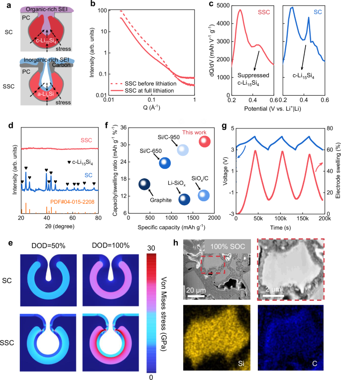
a Schematic illustration of a-LixSi formation enabled by an inorganic-rich SEI and c-Li15Si4 formation enabled by an organic-rich SEI. b SAXS tests of SSC before and after lithiation. c Differential capacity plots of SC and SSC negative electrodes during the first delithiation cycle in the voltage range of 0.2–0.6 V at a specific current of 0.075 A g−1 at ambient temperature. d XRD patterns of SC and SSC negative electrodes in the fully lithiated state. e Finite element simulations of Von Mises stress distribution in SC and SSC negative electrodes at DOD of 50% and 100%. f Performance comparison between SSC negative electrodes and other commercial negative electrodes. The capacity/swelling ratio is defined as the ratio of the first reversible specific capacity of the negative electrodes to the electrode swelling rate at full lithiation (refer to Supplementary Table 4). g In situ electrode swelling behavior and voltage profiles of SSC negative electrodes in a cell during cycling. The rest time is ignored. h Cross-sectional SEM images and corresponding EDS mapping of SSC negative electrodes at full lithiation state.
The mechanical stability advantage of SSC negative electrodes is demonstrated through a comprehensive comparison of reversible specific capacity and electrode swelling at the full lithiation state between the SSC negative electrodes and other practical negative electrodes in LIBs. The electrode expansion was tested under the same conditions where the areal capacity of negative electrodes is fixed at a practical level of 4 mAh cm−2. Additionally, a pressure of 15 tons was applied to all negative electrodes to minimize the internal interparticle porosity. After complete lithiation, achieved by discharging to 5 mV with a specific current of 0.075 A g−1, the electrode thickness before and after alloying were measured using a height gauge to ensure consistent downward pressure rather than using scanning electron microscope (SEM), as electrode thickness measured by SEM can be easily misgauged by sample damage or localized observation72. As a result, the SSC negative electrode presented minimal electrode swelling (57%) compared to other practical negative electrodes in LIBs, as shown in Supplementary Fig. 17a, b. In-situ electrode expansion measurements were conducted on SSC negative electrodes paired with LiNi0.8Co0.1Mn0.1O2 (NCM811) positive electrodes, with an N/P ratio of 1.1 and an areal capacity of 4 mAh cm−2. As depicted in Fig. 4g, SSC||NCM811 cells deliver 58% electrode expansion at full state of charge, which basically meets the requirements for commercialization applications in high-energy LIBs. As shown in Supplementary Fig. 17c, the SSC exhibits comprehensive performance in terms of high reversible specific capacity (1773 mAh g−1), low electrode expansion (58%) and high ICE (93.6%). A high volumetric capacity of 1897 mAh cm−3 was delivered based on the mass loading (2.25 mg cm−2) and thickness (25 μm) of the electrode before cycling. Despite the slightly lower electrode expansions of the Si/C-650 (36%) and Si/C-950 (45%), the effective capacity/swelling ratio of SSC is much higher than these two Si/C negative electrodes and nearly double that of the graphite negative electrode (Fig. 4f).
To investigate the morphological evolution of SSC structure upon battery operation (a cell with SSC as the working electrode, and the lithium (Li) metal foil as the counter electrode), FIB-prepared cross-sections of the SSC negative electrodes were analyzed. As seen in Fig. 4h and Supplementary Fig. 18, there are no cracks in the micro-sized SSC negative electrode particles after fully alloying and dealloying. Specifically, the C element distribution (marked blue) in Fig. 4h demonstrated an intact carbon framework without crack expanded by the Li-Si alloy, while the uniform Si element distribution (marked yellow) indicates a stable Si structure without obvious deficiency after lithiation. Further analysis of the SC and SSC negative electrodes’ microstructure via cross-sectional SEM after 20 cycles (Supplementary Fig. 19) revealed no particle fracture in the SSC negative electrode, with the binder-conductive agent network remaining intact, confirming the structural stability of the SSC. Moreover, Supplementary Fig. 20 highlights the notable presence of F elements, characteristic of the inorganic-rich SEI, on the internal surface of the SSC. This observation confirms the formation of inorganic-rich SEI within the pores in the SSC negative electrode, as a result of solvent pre-desolvation induced by the sieving-pore structure. Supplementary Fig. 21 presents top-view SEM images of SSC after various cycle counts, showing no significant cracking even after 200 cycles, further affirming the SSC negative electrode’s stability.
Electrochemical performances
To verify the electrochemical advantages of the SSC enabled by its kinetic and mechanical stability, the electrochemical performance of the SSC negative electrode was evaluated. The coin-type cells were assembled using Li as the counter electrode, with the voltage ranging from 0.005 V to 2 V for the first two cycles and 0.005 V to 1 V for the following cycles. A prolonged cycle life after 200 cycles at 0.75 A g−1 specific current is obtained with a high reversible areal capacity of 2.0 mAh cm−2 and a high 97% capacity retention (normalized to the 3rd cycle’s areal capacity after activation, the capacity fade is 0.015% per cycle), in stark contrast with SC negative electrodes (the capacity retention decays to 80% within 95 cycles) in Fig. 5a. The discharging-charging curves of the SSC negative electrode from the 3rd to the 100th cycle show a minimal change, while those of SC negative electrodes exhibit obvious capacity fading (Figs. 5b and d), indicating improved mechanical stability and electrode kinetics of SSC negative electrodes. Notably, the cyclic stability and ICE of the SSC negative electrode surpass the reported representative Si negative electrodes (Fig. 5c). Supplementary Fig. 22 and Supplementary Fig. 23 show the ex-situ EIS measurement of SSC and SC negative electrodes at various cycles. The fitting results are shown in Supplementary Fig. 24 that the Li+ transport resistance in SEI (Rint) of the SSC negative electrode (approximately 5–8 Ω) is almost unchanged at whole measurements, appearing to be smaller than that of the SC negative electrode (larger than 20 Ω and gradually increased) during the long-term cycling. Even for electrodes at high loadings from 3 to 11 mg cm−2 and approaching a very high areal capacity of 21.5 mAh cm−2, the SSC cell still works at a stably high specific capacity of ~1800 mAh g−1 (Supplementary Fig. 25), confirming the mechanical robustness of the SSC negative electrode.
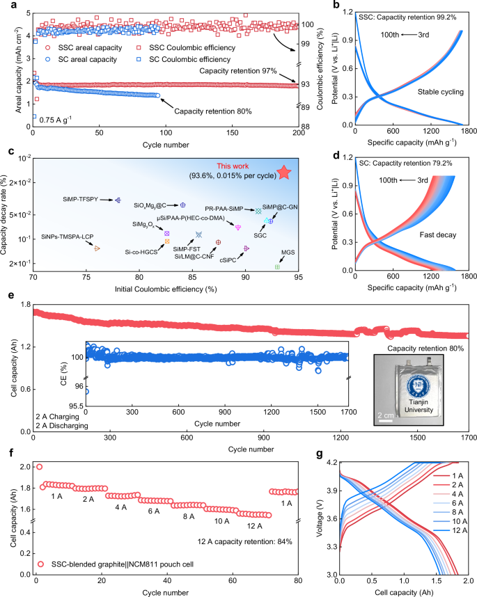
a Cycling performance of the SC and the SSC negative electrodes. The charge/discharge specific current is 0.075 A g−1 for the first two cycles and 0.75 A g−1 for later cycles. Capacity retention is defined as the ratio of specific capacity in the final cycle to that in the third cycle. b, d The corresponding charge-discharge profiles of SSC-based (b) and SC-based (d) cells from 3rd to 100th cycles. Capacity retention is defined as the ratio of specific capacity in the final cycle to that in the third cycle. c Comparisons of the initial Coulombic efficiency versus capacity decay rate between this work and previously reported representative results (refer to Supplementary Table 3). The capacity decay rate is defined as the ratio of the relative capacity loss (defined as the difference between the post-activation and final specific capacities normalized to the post-activation specific capacity) to the total number of cycles. e Cycling performance of Ah-level SSC-blended graphite||NCM811 pouch cell. The charge/discharge current is 2 A charging and 2 A discharging in 3–4.2 V for 1700 cycles. The inset image shows the cyclic CE, and the inset photo shows the assembled pouch cell. Capacity retention is defined as the ratio of capacity in the final cycle to that in the third cycle. f The rate performance of Ah-level SSC-blended graphite||NCM811 pouch cell under different currents from 1 A to 12 A. Capacity retention is defined as the ratio of capacity at 12 A to that at 1 A. g Corresponding charge-discharge profiles of SSC-blended graphite||NCM811 pouch cell under different currents from 1 A to 12 A.
Additionally, the rate capabilities of SC and SSC negative electrodes were measured at various specific currents from 0.2 to 6 A g−1 in Supplementary Fig. 26. Specifically, the SC negative electrode contributes negligible capacity at 6 A g−1, while the SSC negative electrode maintains a specific capacity of nearly 750 mAh g−1 due to the improved Li+ transport ability. When the specific current is returned to 0.2 A g−1, the specific capacity of the SC negative electrode cannot return to its previous level, indicating that the occurrence of severe side reactions leads to significant decay of active Li and the generation of “dead Si”. In contrast, there is no obvious difference in the specific capacity of the SSC negative electrode after changing the specific currents, attributable to the enhanced electrode kinetics. The practical applicability of the SSC negative electrode was evaluated in an Ah-level pouch cell, combining SSC with graphite (the specific capacity is 420 mAh g−1), paired with an NCM811 positive electrode (N:P ratio of 1.15). The pouch cell achieves a stable cycling with an initial capacity of 1.544 Ah and capacity retention of 80% after 1700 cycles at 2 A, indicating strong potential for practical LIB applications (Fig. 5e). The fast-charging capability is also an important criterion for evaluating the commercial viability of SSC negative electrodes. This pouch cell demonstrates a 10-min fast charging performance. The capacity at 12 A maintains 84% of its capacity at 1 A (Fig. 5f). Besides, the corresponding fast-charging curves are shown in Fig. 5g, demonstrating a small gap in cell capacity at different currents. Overall, the SSC negative electrode with low electrode swelling and inner inorganic-rich SEIs simultaneously affords improved cycling performance and fast-charging ability in practical cells, demonstrating its potential for application in high-energy LIBs.
Discussion
In this work, we demonstrate a design rationale for practical Si negative electrodes, effectively integrating mechanical stability with fast kinetics through a sieving-pore structure. This structure features a nanopore body to accommodate Si deformation and a sub-nanometer pore entrance (0.35–0.5 nm) for sieving ions, unlocking stable, fast (de)alloying chemistries. The SSC negative electrode achieves low electrode swelling (58%) and high ICE (93.6%) at a high specific capacity (1773 mAh g−1), together with minimal capacity decay (0.015% per cycle). A practical pouch cell shows stable cycling for over 1700 cycles and fast charging capability. These achievements are attributed to the sieving effect that induces Li+ pre-desolvation, enabling fast intrapore Li+ transport and creating a favorable solvation environment for inorganic-rich SEI formation. Critically, the formation of c-Li15Si4 is significantly suppressed by the mechanical confinement and stress-voltage coupling effects. Our strategy, distinct from conventional designs, offers a paradigm for addressing the inherent trade-offs between capacity, stability, and interfacial kinetics in Si negative electrodes, paving the way for developing better battery materials.
Methods
Material synthesis
The original PCs for SSC preparation were purchased from Changzhou Beiyang New Energy Technology Co., Ltd and subsequently modified by NaCun (Tianjin) Technology Co., Ltd. SSC samples were prepared via a two-step CVD process using a rotatable furnace. First, silicon was deposited onto PCs by thermal decomposition of high-purity monosilane gas (SiH4) (99.9999%) at 450 °C and a flow of 20 L min−1 for 450 min. Subsequently, a sieving carbon layer was deposited using high-purity acetylene (C2H2) gas (99.9%) at 600 °C and a flow rate of 5 L min−1 for 100 min. SC samples were prepared using the same Si deposition process, but without the sieving carbon coating step.
Material characterization
SEM images were obtained using a Hitachi S4800 instrument with an EDS detector (Bruker X-Flash 6/60 series) to analyze the morphology. TEM images were captured using a JEOL JEM 2100 F operating at 200 kV. Ion sputtering was performed with a Ga+ FIB on a ZEISS Crossbeam 540/SEM (Tescan GAIA3). Aberration-corrected HAADF-STEM and EELS analyses were performed using an FEI Talos F200X microscope equipped with an X-FEG field emission gun and a GIF Quantum 965 EELS spectrometer. These techniques were employed to characterize the SSC negative electrode after cycling, providing direct evidence for the formation of an inorganic-rich SEI within the pores. N2 adsorption-desorption at 77 K and CO2 adsorption-desorption experiments at 273 K were conducted using a physisorption analyzer (JW-BK200C). The SSA and pore diameter distribution were analyzed with the BET method and the NLDFT method, respectively. XRD was carried out on a Rigaku D/Max 2500 PC diffractometer using Cu Ka radiation (λ = 1.54056 Å) and Raman spectra were recorded on a MicroRaman system (LabRAM HR spectrometer, Horiba). SAXS was performed using a Xeuss 2.0 SAXS/WAXS System with a Cu X-ray source of 30 W (wavelength = 0.1542 nm). The SAXS data were analyzed using the SasView 4.2.2 software. A height gauge was used to measure the thicknesses of the electrodes before and after cycling in an argon-filled glove box (both oxygen and water contents below 1.0 ppm) at ambient temperature, where the cells were disassembled, and the electrodes were rinsed with dimethyl carbonate (DME). XPS measurements were performed with a Kratos Analytical spectrometer at ambient temperature with monochromatic Al Kα (1486.6 eV) radiation. The preparation of all post-cycling electrodes for testing was performed in an Ar-filled glove box (with both oxygen and water contents below 1.0 ppm) at ambient temperature. After cell disassembly, the electrodes were carefully retrieved and rinsed three times with DME to remove residual electrolyte, followed by vacuum drying to evaporate any remaining solvent. During sample transfer, the electrodes were sealed in a transfer chamber under an Ar atmosphere. Exposure to ambient air was limited to approximately 10–30 s during the transfer to the characterization equipment; all other operations were carried out under an inert Ar environment. The 7Li NMR experiments were performed on a Bruker AVANCE III 400 MHz spectrometer with a 2.5 mm double-resonance HX probe.
The calculation of activation energy
The activation energy was calculated based on the law of Arrhenius.
$$k=A\exp (-\frac{{E}_{a}}{{RT}})$$
(1)
where k is the reaction rate constant, T is the temperature (in Kelvin), Ea is the activation energy, R is the molar gas constant, and A is the pre-exponential factor. By taking the natural logarithm of both sides, the equation becomes:
$${{\mathrm{ln}}}k=-\frac{{E}_{a}}{{RT}}+{{\mathrm{ln}}}A$$
(2)
This expression indicates a linear relationship between \({\mathrm{ln}}k\) and \(1/T\), where the slope equals \(-{E}_{a}/R\). Therefore, \({E}_{a}\) can be determined by fitting a straight line to the plot of \({\mathrm{ln}}k\) versus \(1/T\).
For electrochemical reactions, the reciprocal of the impedance value can be used in place of the rate constant for fitting. The potentiostatic EIS measurements were conducted using an electrochemical workstation (Eco Chemie Autolab) in the frequency range 100 kHz to 0.01 Hz with an amplitude of 10 mV at 25 ± 1 °C in ambient air. A total of 71 points were collected. Prior to EIS testing, the system was stabilized under a quasi-stationary potential for 600 s. The scientific graphing and EIS data analysis were conducted using Origin and ZView software, respectively. The cells were pre-cycled at a specific current of 0.075 A g−1 for the initial two cycles and 0.75 A g−1 for the subsequent eight cycles to ensure stable SEI formation at room temperature before performing EIS measurements over a series of gradient temperatures. It should be noted that the temperature range for fitting should be narrow enough to maintain linearity. The impedance for desolvation (Rct) and Li+ transport through SEI (Rint) were extracted from the Nyquist plots. The activation energy \({E}_{a}\) was determined from the linear relationship between ln(1/R) and \(1/T\) using the Arrhenius equation.
Finite element simulation
Finite element model was employed to investigate the electrochemical and mechanical behavior of different structures using COMSOL Multiphysics 6.0 platform. The simulations captured the evolution of the electric field, Li+ concentration field, and stress field of different Si-C structures during lithiation. The mass transport of Li+ in the electrolyte was governed by the classical Nernst-Plank equation, expressed as:
$${J}_{{{Li}}^{+}}=-{D}_{{{Li}}^{+}}\left(\nabla {c}_{{{\mbox{Li}}}^{+}}+\frac{F{c}_{{{\mbox{Li}}}^{+}}}{{RT}}\nabla {\varPhi }_{{\mbox{e}}}\right)$$
(3)
where \({D}_{{{Li}}^{+}}\) is the diffusion coefficient of Li+, \({J}_{{{Li}}^{+}}\) is the ions flux, \({c}_{{{\mbox{Li}}}^{+}}\) is the concentration of species Li+, and \({\varPhi }_{{\mbox{e}}}\) is the electrolyte potential.
The Faradaic reaction was defined at the Si layer surface with a discharge cutoff voltage of 5 mV. Upon reaction, Li+ was converted to Li0 on the surface of the Si layer and diffused within the Si layer. The diffusion process of Li0 was governed by Fick’s Second Law. The Si layer was assumed to undergo ~300% volume expansion upon full lithiation, which significantly influenced the distribution of the stress field in the solid phaseF.
Electrochemical measurements
The Si electrode slurry was prepared using deionized water (resistivity > 18.0 MΩ·cm at 25 °C) as the solvent in a planetary mixer (Kurabo, KK-250S) at 25 ± 1 °C in ambient air. The slurry composition contained 4.5 g of active material (SSC, SC, or PC samples), 0.12 g of sodium carboxymethyl cellulose (Aladdin, 99.9% purity, molecular weight: 180), 0.26 g of styrene butadiene rubber (Aladdin, 50% solid content, molecular weight: 158), and 0.25 g of carbon black (Super P, TIMCAL, 99%), corresponding to a mass ratio of 90:2.4:2.6:5, respectively. Working electrodes were prepared by casting the slurry onto one side of a copper current collector (Cu, purchased from Guangdong Canrd New Energy Technology Co., Ltd; used as received without further treatment; 9 μm thickness; 5 cm lateral dimension) using a doctor blade. All negative electrodes were dried at 80 °C for 2 h, calendered under a pressure of 15 tons by an electric rolling press (MSK-2150, Shenzhen Kejing Star Technology Company), subsequently punched into 12 mm diameter discs (the area is 1.13 cm2) by a manual disc cutter (MSK-T10, Shenzhen Kejing Star Technology Company), and then vacuum-dried at 110 °C overnight before being transferred to an inert Ar gas environment. The calendered thicknesses of the SC and SSC negative electrodes were controlled at approximately 12 μm and 14 μm, respectively. The areal capacities of PC (mass loading 3.79 mg cm−2), SC (mass loading 0.94 mg cm−2), and SSC (mass loading 1.05 mg cm−2) were controlled at approximately 2 mAh cm−2. Coin-type 2032 cells (purchased from Guangdong Canrd New Energy Technology Co., Ltd.) were assembled using stainless steel cell cases (316 grade) with a diameter of 20 mm and a thickness of 3.2 mm. Each cell was equipped with a wave spring (diameter: 15.4 mm, thickness: 1.0 mm) and a spacer (diameter: 15.8 mm, thickness: 1.0 mm). Assembly was conducted in an argon-filled glove box (O2 and H2O contents <1.0 ppm), using Li metal foil (Guangdong Canrd, >99.9% purity, 14 mm diameter, 1 mm thickness) as the counter electrode. The Li foil was directly used without further treatment and stored in the argon-filled glove box (O2 and H2O contents <1.0 ppm) at ambient temperature for no more than six months prior to use. The electrolyte was 1.0 M LiPF6 in ethylene carbonate/diethyl carbonate (1:1 vol%) with 10% fluoroethylene carbonate, directly purchased from DoDoChem and stored in an aluminum bottle (less than 1 month) inside the above Ar-filled glovebox (O2 and H2O contents <1.0 ppm) at ambient temperature. During cell assembly, the electrolyte (30 μL total) was added using a polypropylene (PP) pipette tip. Specifically, 15 μL was dropped onto the negative electrode, the separator was then placed, and an additional 15 μL was added on top to ensure full wetting. A commercial Celgard 2325 separator (PP/Polyethylene, PE/PP, thickness: 25 μm, porosity: 39%, average pore size: 0.025 μm, lateral dimension: 100 mm) was used. The separator was punched into 16 mm diameter discs using a manual disc cutter and vacuum-dried at 100 °C overnight before use. Electrochemical properties of these cells were evaluated on a Neware battery cycler (CT-4008Tn-5V10mA, Shenzhen, China) at 25 ± 1 °C in ambient air, using a constant current protocol under the voltage window between 0.005 and 2 V for the first two cycles at a specific current of 0.075 A g−1, and between 0.005 and 1.0 V for the rest of the cycles at a specific current of 0.75 A g−1. The specific current and specific capacity are calculated based on the mass of the active material.
For the pouch cell test, the SSC-blended graphite negative electrodes (mass loading 6.26 mg cm−2) were paired with an NCM811 positive electrode (custom-fabricated and purchased from Guangdong Canrd New Energy Technology Co., Ltd and the mass loading is 12 mg cm−2) with an N/P ratio of ~1.15. Detailed cell design parameters are provided in Supplementary Table 5. The cells were assembled in a dry room (a dew point below −40 °C). The constant temperature for the cell test is maintained by a thermostat, which automatically adjusts to restore the preset temperature in the event of a program error. Although the program error induced temperature change causes the capacity fluctuations in Fig. 5e, it does not impact the long-term stability demonstrated in the cycling tests or alter the conclusion regarding the extended durability of our cells. Battery performance was tested using a constant current-constant voltage (CC-CV) protocol on a Neware battery cycler (BTS4000-5V20A, Shenzhen, China) at 25 ± 1 °C in ambient air within a voltage window of 3.0–4.2 V under a constant external stack pressure of 300 kPa. The charging current was set to 0.2 A for the initial cycle and 2 A for subsequent cycles. During the constant voltage stage, charging was sustained until the current declined to below 10% of the preset value. The discharge current was set to 0.2 A for the first cycle and 2 A for the following cycles, consistent with the charging protocol. For rate capability evaluation, the cells were charged using the CC-CV mode at currents of 1, 2, 4, 6, 8, 10, and 12 A. In each current, the constant voltage step was maintained until the current decreased to below 10% of the applied current. The corresponding discharge current was matched to the charge current in each cycle.
Note:
Specific current (mA g−1) = (applied current in mA) / (mass of Si/C in g)
Specific capacity (mAh g−¹) = (discharge capacity in mAh) / (mass of Si/C in g)
Areal capacity (mAh cm−²) = (discharge capacity in mAh) / (area of the electrode in cm²)
Current density (mA cm−2) = (applied current in mA) / (area of the electrode in cm²)
Volumetric capacity (mAh cm−3) = (discharge capacity in mAh) / (volume of the electrode in cm³)
The Coulombic efficiency (CE) was defined as the ratio of charge capacity to discharge capacity in each cycle for coin cells, whereas for pouch cells, CE was determined as the ratio of discharge capacity to charge capacity in the corresponding cycle.
Data availability
All data are available in the main text and the supplementary information. Source data are provided with this paper.
References
McBrayer, J. D. et al. Calendar aging of silicon-containing batteries. Nat. Energy 6, 866–872 (2021).
Choi, S. et al. Highly elastic binders integrating polyrotaxanes for silicon microparticle anodes in lithium ion batteries. Science 357, 279–283 (2017).
Pendashteh, A. et al. Nanotextile 100% Si anodes for the next generation energy-dense Li-ion batteries. Adv. Energy Mater. 14, 2304018 (2024).
Obrovac, M. N. & Chevrier, V. L. Alloy negative electrodes for Li-ion batteries. Chem. Rev. 114, 11444–11502 (2014).
Shi, F. et al. Failure mechanisms of single-crystal silicon electrodes in lithium-ion batteries. Nat. Commun. 7, 11886 (2016).
Lahiri, A. & Endres, F. Electrodeposition of nanostructured materials from aqueous, organic and ionic liquid electrolytes for Li-ion and Na-ion batteries: a comparative review. J. Electrochem. Soc. 164, D597 (2017).
Zhao, Z. et al. Revival of microparticular silicon for superior lithium storage. Adv. Energy Mater. 13, 2300367 (2023).
Liu, X. H. et al. Size-dependent fracture of silicon nanoparticles during lithiation. ACS Nano 6, 1522–1531 (2012).
Li, A. M. et al. High voltage electrolytes for lithium-ion batteries with micro-sized silicon anodes. Nat. Commun. 15, 1206 (2024).
Pan, S. et al. Integrating SEI into layered conductive polymer coatings for ultrastable silicon anodes. Adv. Mater. 34, 2203617 (2022).
Zhao, Z. et al. Liquid metal remedies silicon microparticulates toward highly stable and superior volumetric lithium storage. Adv. Energy Mater. 12, 2103565 (2022).
Tan, D. H. S. et al. Carbon-free high-loading silicon anodes enabled by sulfide solid electrolytes. Science 373, 1494–1499 (2021).
Zhai, Y. et al. Both resilience and adhesivity define solid electrolyte interphases for a high performance anode. J. Am. Chem. Soc. 146, 15209–15218 (2024).
Fang, Q. et al. Interfacial degradation of silicon anodes in pouch cells. Energy Environ. Sci. 17, 6368–6376 (2024).
Vorauer, T. et al. Impact of solid-electrolyte interphase reformation on capacity loss in silicon-based lithium-ion batteries. Commun. Mater. 4, 44 (2023).
Vorauer, T. et al. Multi-scale quantification and modeling of aged nanostructured silicon-based composite anodes. Commun. Chem. 3, 141 (2020).
Häusler, M. et al. Amorphous shear band formation in crystalline silicon-anodes governs lithiation and capacity fading in Li-ion batteries. Commun. Mater. 5, 163 (2024).
Cheng, K. et al. Material-electrolyte interfacial interaction enabling the formation of an inorganic-rich solid electrolyte interphase for fast-charging Si-based lithium-ion batteries. Energy Environ. Sci. 17, 2631–2641 (2024).
Lauro, S. N. et al. Restructuring the lithium-ion battery: a perspective on electrode architectures. eScience 3, 100152 (2023).
Park, S. et al. Scalable synthesis of hollow β-SiC/Si anodes via selective thermal oxidation for lithium-ion batteries. ACS Nano 14, 11548–11557 (2020).
Li, Y. et al. Growth of conformal graphene cages on micrometre-sized silicon particles as stable battery anodes. Nat. Energy 1, 1–9 (2016).
Cao, C. et al. Solid electrolyte interphase on native oxide-terminated silicon anodes for Li-ion batteries. Joule 3, 762–781 (2019).
Zhang, H. et al. SiO-Sn2Fe@C composites with uniformly distributed Sn2Fe nanoparticles as fast-charging anodes for lithium-ion batteries. eScience 3, 100080 (2023).
Chan, C. K. et al. High-performance lithium battery anodes using silicon nanowires. Nat. Nanotechnol. 3, 31–35 (2008).
An, W. et al. Scalable synthesis of ant-nest-like bulk porous silicon for high-performance lithium-ion battery anodes. Nat. Commun. 10, 1447 (2019).
Xu, D. X. et al. Reduced volume expansion of micron-sized SiOx via closed-nanopore structure constructed by Mg-induced elemental segregation. Angew. Chem. Int. Ed. 63, e202401973 (2024).
Tian, Y. F. et al. Micrometer-sized SiMgyOx with stable internal structure evolution for high-performance Li-ion battery anodes. Adv. Mater. 34, 2200672 (2022).
Han, J. et al. Caging tin oxide in three-dimensional graphene networks for superior volumetric lithium storage. Nat. Commun. 9, 402 (2018).
Chen, F. et al. 1000 Wh L−1 lithium-ion batteries enabled by crosslink-shrunk tough carbon encapsulated silicon microparticle anodes. Natl. Sci. Rev. 8, nwab012 (2021).
Ma, D. D. D. et al. Small-diameter silicon nanowire surfaces. Science 299, 1874–1877 (2003).
He, Y. et al. Progressive growth of the solid-electrolyte interphase towards the silicon anode interior causes capacity fading. Nat. Nanotechnol. 16, 1113–1120 (2021).
Jia, H. et al. Hierarchical porous silicon structures with extraordinary mechanical strength as high-performance lithium-ion battery anodes. Nat. Commun. 11, 1474 (2020).
Li, Z. et al. Covalent coating of micro-sized silicon with dynamically bonded graphene layers toward stably cycled lithium storage. Adv. Energy Mater. 13, 2300874 (2023).
Liu, N. et al. A pomegranate-inspired nanoscale design for large-volume-change lithium battery anodes. Nat. Nanotechnol. 9, 187–192 (2014).
Wu, H. et al. Stable cycling of double-walled silicon nanotube battery anodes through solid-electrolyte interphase control. Nat. Nanotechnol. 7, 310–315 (2012).
Su, X. et al. Silicon-based nanomaterials for lithium-ion batteries: a review. Adv. Energy Mater. 4, 1300882 (2014).
He, Z. et al. The acupuncture effect of carbon nanotubes induced by the volume expansion of silicon-based anodes. Energy Environ. Sci. 17, 3358–3364 (2024).
Sung, J. et al. Subnano-sized silicon anode via crystal growth inhibition mechanism and its application in a prototype battery pack. Nat. Energy 6, 1164–1175 (2021).
Chae, S. et al. Gas phase synthesis of amorphous silicon nitride nanoparticles for high-energy LIBs. Energy Environ. Sci. 13, 1212–1221 (2020).
Li, Q. et al. Sieving carbons promise practical anodes with extensible low-potential plateaus for sodium batteries. Natl. Sci. Rev. 9, nwac084 (2022).
Kim, N. et al. Fast-charging high-energy lithium-ion batteries via implantation of amorphous silicon nanolayer in edge-plane activated graphite anodes. Nat. Commun. 8, 812 (2017).
Saurel, D. et al. A SAXS outlook on disordered carbonaceous materials for electrochemical energy storage. Energy Storage Mater. 21, 162–173 (2019).
Chen, X. et al. Filling carbon: a microstructure-engineered hard carbon for efficient alkali metal ion storage. Energy Environ. Sci. 16, 4041–4053 (2023).
Thommes, M. et al. Physisorption of gases, with special reference to the evaluation of surface area and pore size distribution. Pure Appl. Chem. 87, 1051–1069 (2015).
Garrido, J. et al. Use of nitrogen vs. carbon dioxide in the characterization of activated carbons. Langmuir 3, 76–81 (1987).
Jagiello, J. & Thommes, M. Comparison of DFT characterization methods based on N2, Ar, CO2, and H2 adsorption applied to carbons with various pore size distributions. Carbon 42, 1227–1232 (2004).
Zhang, L. et al. DFT modeling of CO2 and Ar low-pressure adsorption for accurate nanopore structure characterization in organic-rich shales. Fuel 204, 1–11 (2017).
Lu, Z. et al. Consummating ion desolvation in hard carbon anodes for reversible sodium storage. Nat. Commun. 15, 3497 (2024).
Xu, J. et al. Electrolyte design for Li-ion batteries under extreme operating conditions. Nature 614, 694–700 (2023).
Lu, D. et al. Ligand-channel-enabled ultrafast Li-ion conduction. Nature 627, 101–107 (2024).
Li, A. M. et al. Asymmetric electrolyte design for high-energy lithium-ion batteries with micro-sized alloying anodes. Nat. Energy 9, 1551–1560 (2024).
Danet, J. et al. Valence electron energy-loss spectroscopy of silicon negative electrodes for lithium batteries. Phys. Chem. Chem. Phys. 12, 220–226 (2010).
Boniface, M. et al. Nanoscale chemical evolution of silicon negative electrodes characterized by low-loss STEM-EELS. Nano Lett. 16, 7381–7388 (2016).
Fleischmann, S. et al. Continuous transition from double-layer to Faradaic charge storage in confined electrolytes. Nat. Energy 7, 222–228 (2022).
Lu, Z. et al. Electrolyte sieving chemistry in suppressing gas evolution of sodium-metal batteries. Angew. Chem. Int. Ed. 134, e202206340 (2022).
Lu, Z. et al. Step-by-step desolvation enables high-rate and ultra-stable sodium storage in hard carbon anodes. Proc. Natl. Acad. Sci. USA 119, e2210203119 (2022).
Morales, D. et al. Ion transport and association study of glyme-based electrolytes with lithium and sodium salts. Electrochim. Acta 304, 239–245 (2019).
Åvall, G. et al. Highly concentrated electrolytes: electrochemical and physicochemical characteristics of LiPF6 in propylene carbonate solutions. J. Electrochem. Soc. 168, 050521 (2021).
Han, S.-D. et al. Solvate structures and computational/spectroscopic characterization of LiPF6 electrolytes. J. Phys. Chem. C. 119, 8492–8500 (2015).
Dhumal, N. R. & Gejji, S. P. Theoretical studies on blue versus red shifts in diglyme-M+-X-(M= Li, Na, and K and X= CF3SO3, PF6, and (CF3SO2)2N). J. Phys. Chem. A. 110, 219–227 (2006).
Wang, H. et al. Correlating Li-ion solvation structures and electrode potential temperature coefficients. J. Am. Chem. Soc. 143, 2264–2271 (2021).
Tan, R. et al. Hydrophilic microporous membranes for selective ion separation and flow-battery energy storage. Nat. Mater. 19, 195–202 (2020).
Chen, J. et al. Electrolyte design for LiF-rich solid-electrolyte interfaces to enable high-performance microsized alloy anodes for batteries. Nat. Energy 5, 386–397 (2020).
Li, H. et al. Effects of stress dependent electrochemical reaction on voltage hysteresis of lithium-ion batteries. Appl. Math. Mech. 39, 1453–1464 (2018).
Yang, P. Y. et al. Predicted structural and mechanical properties of activated carbon by molecular simulation. Comp. Mater. Sci. 143, 43–54 (2018).
Sethuraman, V. A. et al. In situ measurements of stress-potential coupling in lithiated silicon. J. Electrochem. Soc. 157, A1253 (2010).
Bärmann, P. et al. Impact of the crystalline Li15Si4 phase on the self-discharge mechanism of silicon negative electrodes in organic electrolytes. ACS Appl. Mater. Inter. 12, 55903–55912 (2020).
Han, S. Y. et al. Stress evolution during cycling of alloy-anode solid-state batteries. Joule 5, 2450–2465 (2021).
Xu, X. et al. Robust silicon/carbon composite anode materials with high tap density and excellent cycling performance for lithium-ion batteries. J. Power Sources 614, 234992 (2024).
Piper, D. M. et al. Effect of compressive stress on electrochemical performance of silicon anodes. J. Electrochem. Soc. 160, 77–81 (2012).
Obrovac, M. N. et al. Structural changes in silicon anodes during lithium insertion/extraction. Electrochem. Solid-State Lett. 7, A93 (2004).
Kim, N. et al. Issues impeding the commercialization of laboratory innovations for energy-dense Si-containing lithium-ion batteries. Nat. Energy 8, 921–933 (2023).
Acknowledgements
The authors appreciate the support from the National Key Research and Development Program of China (No.2021YFF0500600, Q.-H.Y.), the National Natural Science Foundation of China (No. 52272231, S.C.W.) (No. 52202041, J.W.H.) (No. 52402303, X.J.) (No. U2001220, S.C.W.), the Haihe Laboratory of Sustainable Chemical Transformations, Taishan Scholar Project of Shandong Province (tsqn202211086, J.W.H.), and the Natural Science Foundation of Tianjin Municipality (No. 24JCZDJC00400, S.C.W.).
Ethics declarations
Competing interests
The authors declare no competing interests.
Peer review
Peer review information
Nature Communications thanks Roland Brunner and the other, anonymous, reviewer(s) for their contribution to the peer review of this work. A peer review file is available.
Additional information
Publisher’s note Springer Nature remains neutral with regard to jurisdictional claims in published maps and institutional affiliations.
Supplementary information
Rights and permissions
Open Access This article is licensed under a Creative Commons Attribution-NonCommercial-NoDerivatives 4.0 International License, which permits any non-commercial use, sharing, distribution and reproduction in any medium or format, as long as you give appropriate credit to the original author(s) and the source, provide a link to the Creative Commons licence, and indicate if you modified the licensed material. You do not have permission under this licence to share adapted material derived from this article or parts of it. The images or other third party material in this article are included in the article’s Creative Commons licence, unless indicated otherwise in a credit line to the material. If material is not included in the article’s Creative Commons licence and your intended use is not permitted by statutory regulation or exceeds the permitted use, you will need to obtain permission directly from the copyright holder. To view a copy of this licence, visit http://creativecommons.org/licenses/by-nc-nd/4.0/.
About this article
Cite this article
He, J., Deng, Y., Han, J. et al. Sieving pore design enables stable and fast alloying chemistry of silicon negative electrodes in Li-ion batteries. Nat Commun 16, 4858 (2025). https://doi.org/10.1038/s41467-025-60191-9
Received: 16 September 2024
Accepted: 16 May 2025
Published: 25 May 2025
DOI: https://doi.org/10.1038/s41467-025-60191-9