.png)

What?
This is a chonky lamp which can also protect your living room coastline from erosion. And let's be honest, who doesn't like a versatile lamp?
Warning: If you are not comfortable working with mains voltage, seek professional assistance. Also, the electric part of this lamp is according to European standards. In case you are living outside of Europe, please use wiring according to your local standards!
Materials
For this lamp you need the following materials:
- ca. 5kg of transparent Filament (I went for Extrudr PCTG but PETG or likely PLA will also work)
- 4 LED bulbs (I used the IKEA Trådfri with RGB)
- 4 E27 Sockets (these are really cheap but seem to work reasonably so far)
- 1 Power cord
- 1m of 0,75mm² blue cable
- 1m of 0,75mm² black or brown cable
- 8 wire ferrules
- 2 Wago connectors for 5 wires
- 1 white zip tie
- 8 Threaded inserts M4 for the E27 sockets
- 42 Threaded inserts M5 for assembling the central piece and the arm shells
- 8 M4x16 hex socket screws for the E27 sockets
- 18 M5x12 hex socket screws for assembling the central piece
- 18 M5 washers
- 24 M5x10 countersunk white nylon screws for mounting the arm shells
All items which are directly linked are either the exact material I used or similar so they should work without any issues.
Tools
For assembly, the following tools are needed:
- Soldering iron with an insert installation tip
- Box cutter of any other kind of craft knife for cleanup of parts
- wire cutter
- wire stripper
- crimping pliers
- 3mm hex key
- 4mm hex key
- PH2 screwdriver
Printing
For this tetrapod lamp you need to print 3 different pieces:
- 4 pcs. arm shell
- 3 pcs. centerpiece side
- 1 pc. centerpiece top
The gcode files for printing on a Prusa XL are privided for PCTG, PETG and PLA with 0,2mm layer height. In total they take about 10 days of printing time!
If you use a different printer, you need at least 310mm in Z and 255mm in X and Y. The STLs as well as the PrusaSlicer file is included. Use the following settings:
- Wall thickness: >2mm
- Bottom & top thickness: >1,5mm
- Generate support material only for the centerpieces but add support blockers for the sideways facing holes
- Use random seam position on the arm shell (only if your filament doesn't tend to string)
Assembly
First, clean up the supported faces of all 4 centerpieces using the knife. Scape of all small, attached bits of support. Make sure the faces are really smooth so the pieces co go together properly.
Then, put in the threaded inserts into all 4 pieces. I usually work according to the recommendations from CNC Kitchen. The most important take-away is that you should use temperatures 10 - 20 °C higher than you use for printing. And I recommend to use appropriate intallation tips to transfer the temperature better and for easier alignment of the inserts.
Start with the 2 M4 inserts for the E27 fixtures in the center of each piece.
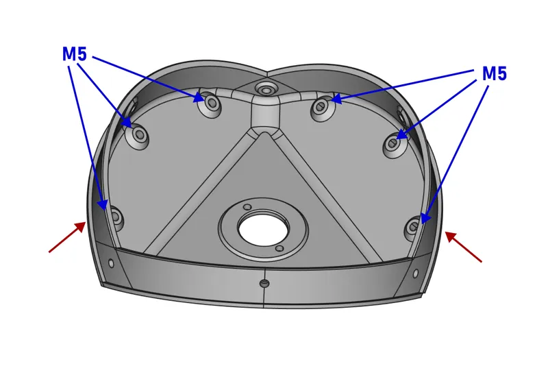
6 M5 inserts get installed into all side-facing holes of each centerpiece.
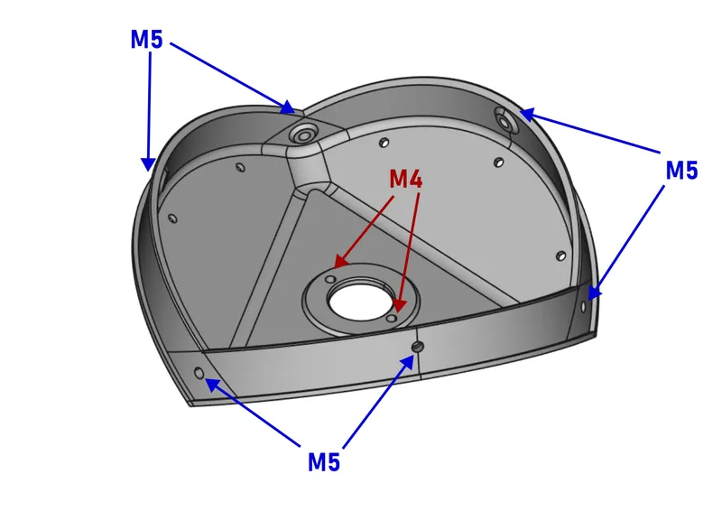
The 3 centerpieces side receive 6 additional M5 inserts on the faces shown in the picture below. Important: Install them from the “bottom” side (red arrow).
Next, prepare the wiring. Cut the fixture from the power cord. Strip the wire ends and put a Wago connector on each wire. Secure the end of the cord with a zip tie about 15cm from the loose end. Assemble the 3 centerpieces side around the power cord as shown in the picture below. Use the M5x12 hex socket screws with a washer but don't fully tighten the pieces yet.
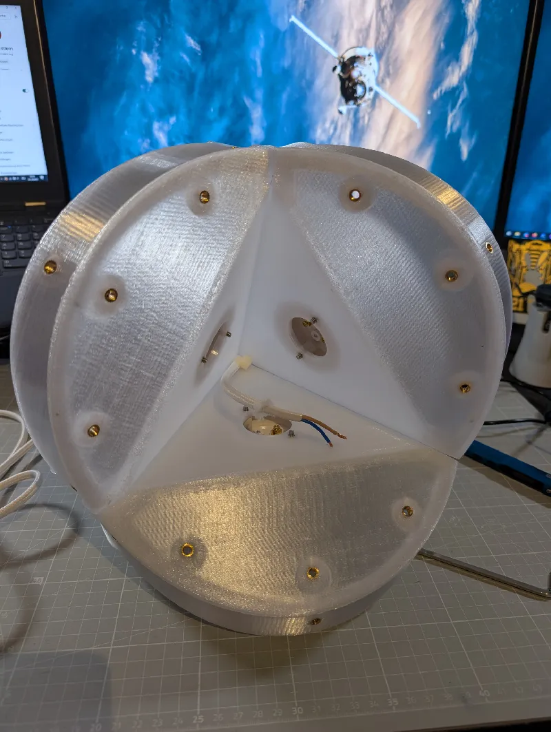
Cut the 0,75mm² cables into 4 pieces, put a ferrule on one end of each wire, strip the other end and put them into the Wago connectors. Feed a black/brown wire and a blue wire through each fixture opening. Install the centerpiece top and put an E27 socket on each pair of wires. The blue wire needs to be connected to the thread, especially when using a polarized plug like in the UK for example.
Mount the fixtures with two M4 screws each and you should have something like in the next picture.
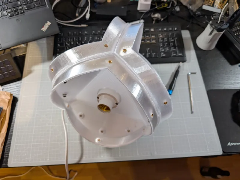
Now you only need to add the bulbs, pair them with your home automation setup (if they are “smart”) and attach the arm shells with 6 M5 nylon screws each using the PH2 screwdriver. Be careful so you don't overtighten them.
Modifying the Design
In case you want to use different fixtures or a thicker/thinner cable, the FreeCAD files are provided as well. The features you need to modify are called “Cable hole” and “E27 socket” so they should be easy to find.
Tags
The author marked this model as their own original creation.