.png)

In April, 2025 Alcor Foundation announced that they had received a patent for a liquid ventilation device.[1] This roused my curiosity, because at that time, so far as I could tell, no one had seen the device in its completed form, or had seen it demonstrated. I had a special interest in the subject, having worked on liquid ventilation intermittently for 20 years. I had even collaborated on it briefly with Steve Graber at Alcor. So—what was going on?
My article here summarizes all the information about liquid ventilation that I have available, and also explains why a seemingly simple concept has never been applied in a cryonics case, even though it may play an important role to improve rapid cooling. If you only want my opinion on the Alcor patent, you can skip to the end of this lengthy text; but to put it in perspective, you might want to know some technical background and some history.
In a previous Substack document, I suggested that immersing a cryonics patient in ice-cold water is necessary but inadequate. Cooling is essential, but the body does not conduct heat very rapidly from the core to the skin, and a faster method than immersion would be highly desirable.
If there was some way to cool the blood inside the body while maintaining circulation, this would be an ideal approach. Indeed, we do something similar in cryonics cases when circumstances permit. Before a patient is transported to a cryonics facility, a surgeon can gain vascular access, enabling blood to be washed out and replaced with a chilled organ preservation solution. This is then circulated through an external heat exchanger.
The problem with this procedure is that we can’t usually do it right away. First the patient must be moved to a suitable location, such as a mortuary, where the surgery can be carried out. Consequently, when all factors are taken into account, a delay of at least two hours between pronouncement and blood washout is likely, and it may be much longer. During this interval, we would prefer to begin internal cooling noninvasively—without surgery—and the best idea that anyone has suggested, to achieve this, is by ventilating the lungs with a chilled liquid while maintaining chest compressions to circulate the blood.
The normal function of the lungs is to facilitate gas exchange, in which oxygen is passed into the blood and carbon dioxide is extracted from the blood. To perform this process, the lungs are divided into alveoli, which are so tiny that about 170 will fit into a cubic millimeter.[2] Their total surface area is often stated as being approximately 100 square meters.[3] This means that the lungs are ideal not only for gas exchange, but for heat exchange.
Liquids generally are much more efficient than gases for conduction of heat, by a factor of 10 or more. For example, water is more thermally conductive than air by a ratio of around 23:1, using samples of identical thickness.[4] Therefore, to cool the blood in the capillaries that permeate the lungs, ideally we would want to use a breathable liquid—and it turns out that a perfluorocarbon liquid can perform this function. It is chemically inert, so it has no undesirable biochemical effects, but at the same time, it can transport oxygen and carbon dioxide.
To implement liquid ventilation in a cryonics case, a paramedic would intubate the patient to gain access to the trachea immediately after pronouncement. This should take less than a minute. Subsequently, we should be able to use some relatively simple equipment to infuse the lungs with chilled perfluorocarbon, and then suction it out, at which point it would be chilled and infused again. This idea was first proposed by Michael Darwin in the 1990s.
The concept is less odd than it may sound, as ventilating the lungs of living mammals with a perfluorocarbon liquid has been performed since 1966, when Leland C. Clark and Frank Gollan demonstrated that mice and cats could be revived without injury after breathing the liquid for up to an hour.[5] This experiment encouraged Johannes Kylstra to pursue using perfluorocarbons for deep-sea divers, to protect them from damage known as “the bends” resulting from pressure changes when the diver rises to the surface.[6] Two decades later, Thomas H. Shaffer became a persistent advocate of perfluorocarbon liquid to treat infants with acute respiratory distress syndrome, as the greater density of the liquid enabled it to displace water in the lungs.[7]
These applications did not involve chilling the liquid, because their goal was not to cool the patient. Darwin’s contribution was to realize that cryonicists could take advantage of liquid ventilation for our own purposes as cryonicists. If the liquid was infused at near 0 degrees Celsius, it could radically improve the cooling rate in cryonics cases. A very early proof-of-concept using pre-cooled cartridges and a peristaltic pump is shown in Figure 1.
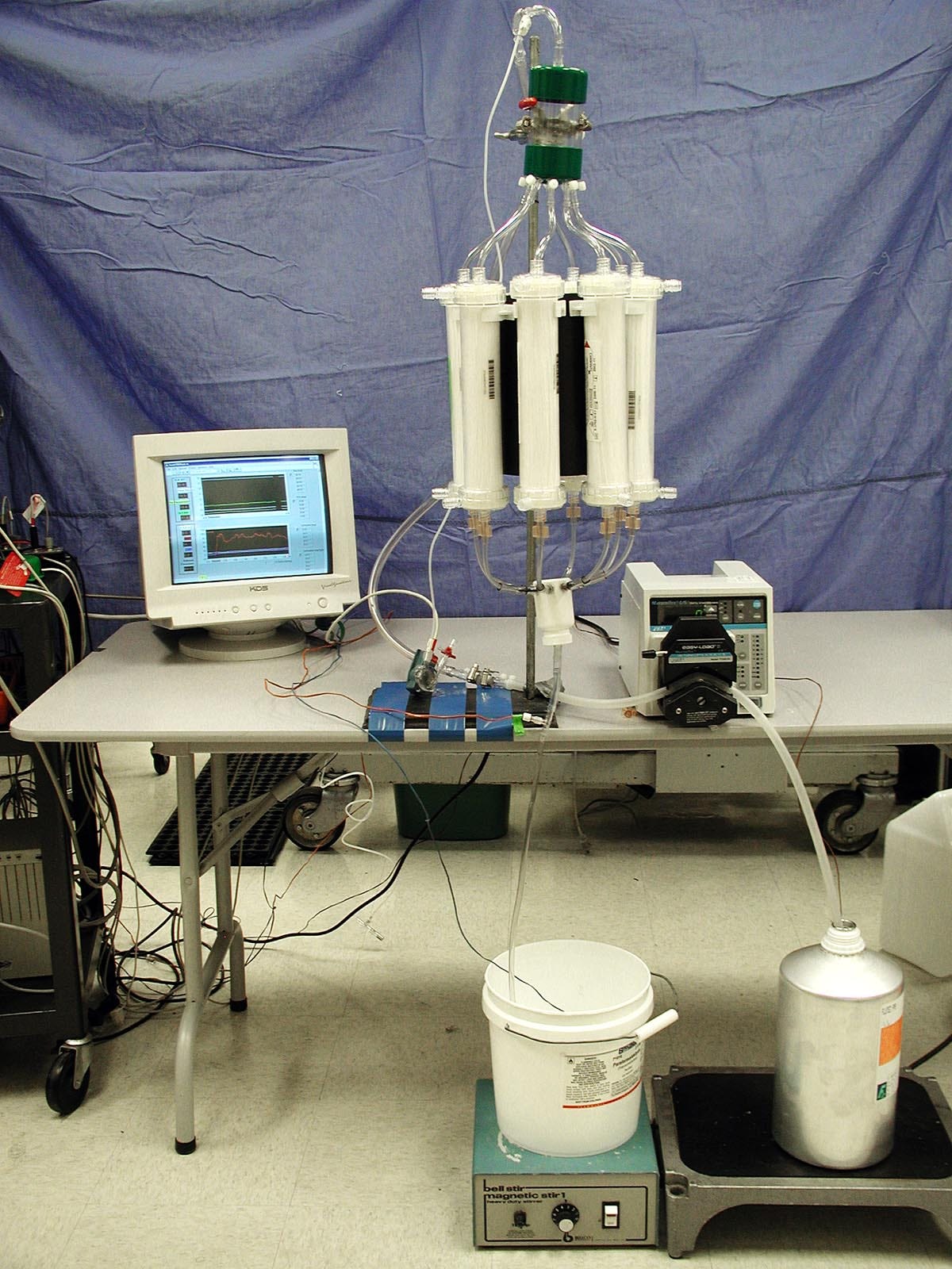
Figure 1. A very early proof-of-concept of liquid ventilation by Michael Darwin.
\
Since liquid ventilation has been used in conventional medicine, and we can easily imagine some simple methods for chilling the liquid, why isn’t the procedure already being used in cryonics? The answer, of course, is that it turns out to be more difficult than it sounds.
Darwin submitted a patent application for improved liquid ventilation equipment in 2000 under his legal name, Michael Federowicz, in collaboration with coworkers Sandra Russell and Steven B. Harris, MD. This was issued as patent US6694977B in February, 2004. It was assigned to Critical Care Research (CCR), the company that employed the researchers.
The patent included a block diagram shown in Figure 2, and sample cooling curves shown in Figure 3. Note that the dogs which were experimental subjects for this research were under total anesthesia, and they fully recovered afterward. Critical Care Research pursued all its research under regulations from relevant agencies.
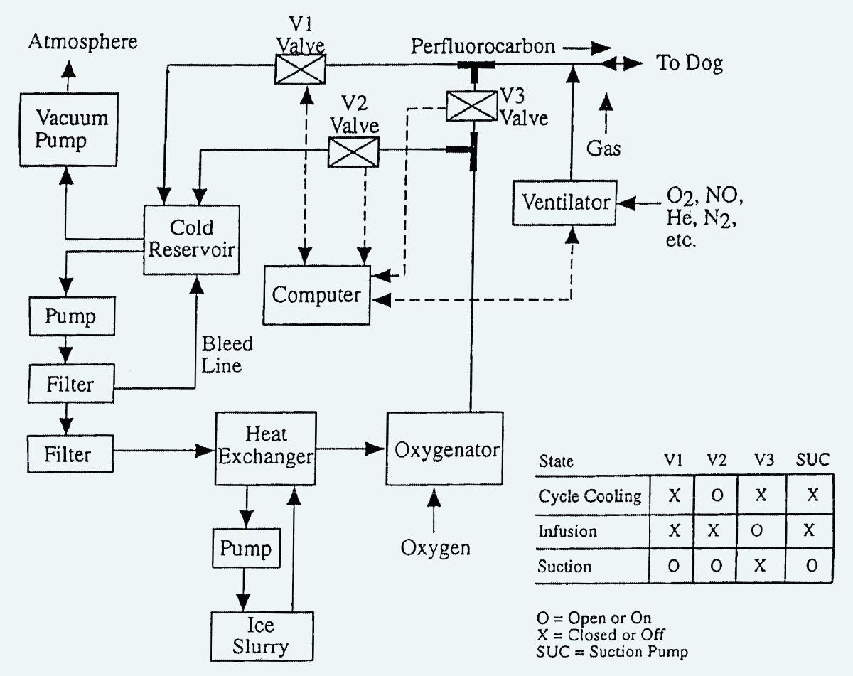
Figure 2. Block diagram from the Critical Care Research patent published in February, 2004.
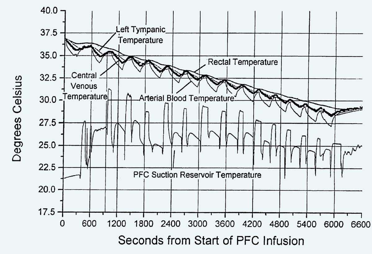
Figure 3. Cooling curves from the Critical Care Research patent published in February, 2004.
In Figure 2, a vacuum pump is used to reduce the pressure in a sealed “cold reservoir,” which will suck liquid out of the lungs when valve V1 is opened under computer control. Liquid from the “cold reservoir” is removed by another pump, before being passed through a heat exchanger and then an oxygenator, at which point it is either circulates back to the reservoir by valve V2, or is introduced into the lungs via valve V3. A ventilator is included because the researchers found that mixing gas into the infusions seemed to disperse the perfluorocarbon liquid more effectively, creating faster cooling rates. An engineering company was employed to build a device conforming with these specifications, but so far as I know, photographs of it have been lost.
In Figure 3, the cooling rate is somewhat disappointing, at around 7.5 degrees Celsius over a period of 100 minutes.
Soon after 2000, I visited Critical Care Research and viewed the equipment. Clearly, it worked, but it suffered from various practical problems. Most obviously it was large, heavy, and depended on bulky peristaltic pumps, often referred to as “roller pumps,” which consume significant power at 110VAC. Neither these pumps nor the rest of the equipment was easily portable, which would be essential if it was to be used during standby-transport work in cryonics.
In addition, there were problems with flow measurement. The laboratory needed experimental data to establish optimal parameters for infusion volume, infusion rate, suction rate, and gas volume, but measuring flow rate is surprisingly difficult when an infusion is brief and the flow is immediately reversed. You get turbulence, which a traditionally designed flow sensor doesn’t deal with very well. The engineering company which built the equipment tried to weigh each infusion, but that didn’t work very well, either.
Eventually Critical Care Research used another company to build a new device, but this had its own problems. So, the employees set up their own improvised version of the equipment, with tubing and ice chests that occupied a lot of floor space, as shown in figures 4 and 5. Again, the system worked, but it was even less portable than its predecessors.
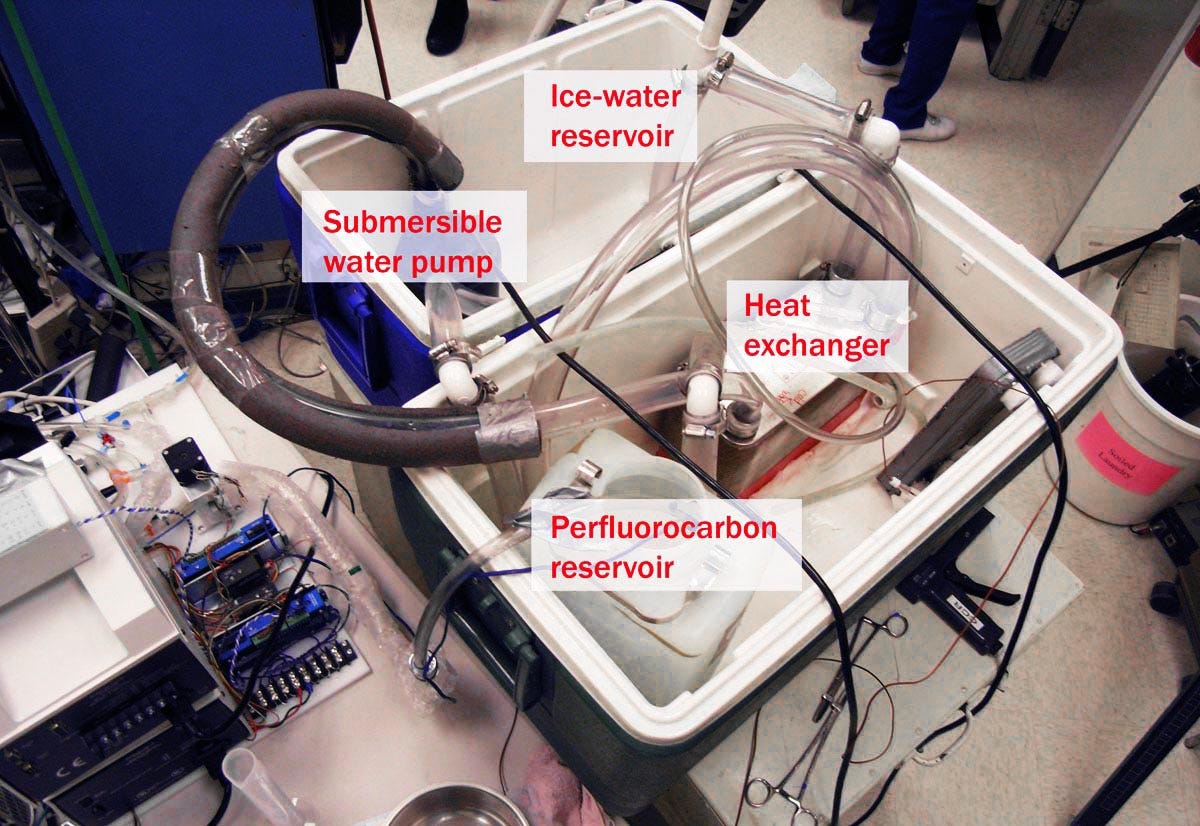
Figure 4. An improvised liquid ventilation setup at Critical Care Research.
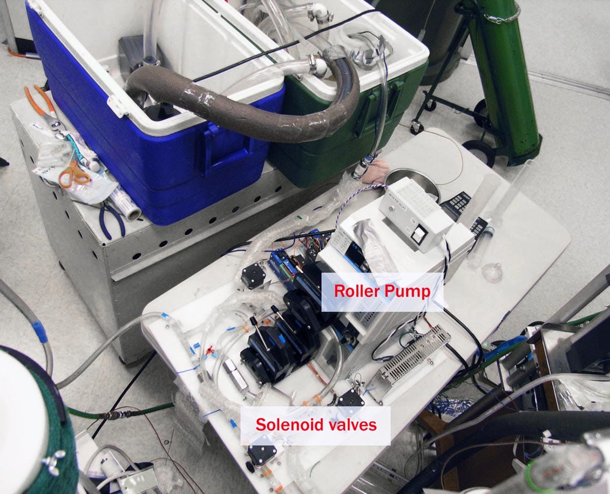
Figure 5. Another view of the equipment in Figure 4.
I was on friendly terms with the people at CCR, and I remember saying, “This shouldn’t be so difficult. I mean, it’s not rocket science.”
Naturally their response was, “If you think it’s so easy, you should try it.”
At that time, I was managing Suspended Animation, a rapid-response cryonics company located in Florida. We were supervised by Saul Kent, who was always willing to take a chance on something that had even a small chance of working, so he told me to go ahead and build my own version of liquid ventilation, which would then be tested at CCR.
My gut feeling was that previous attempts had been unsatisfactory because engineering companies naturally tend to do things in a formal way, which results in complexity. I wanted to make everything much simpler, because it seemed to me that the goal itself was simple.
With this in mind, I established nine principles.
1. The lungs were not sterile, so I wouldn’t need sterile technique. Sterile tubing and peristaltic pumps were unnecessary.
2. The whole system should run off 12VDC, so that it could eventually become portable.
3. Bearing in mind (1) and (2), very lightweight submersible marine bilge pumps could be used, such as the one in Figure 6, rated for 500 gallons per hour, which is about half a liter per second. Of course, this rate assumes that the pump is unloaded, but still it seemed impressive for a little unit weighing under 1 lb and consuming less than 3A at 12VDC.
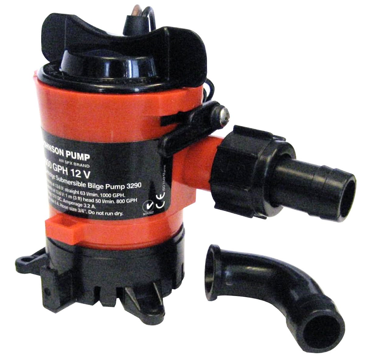
Figure 6. This lightweight centrifugal pump has been used in all my liquid ventilation devices and has proved reliable over a period of more than a decade.
4. Cycle timing could be achieved with a basic 555 timer chip. No computer was required. This was a significant advantage since equipment might receive rough handling if it was transported as checked baggage on an airline.
5. I decided to postpone the problem of accurate volume measurement until I found out if initial results from the equipment were encouraging. Meanwhile, the cycle time could determine the volume of each infusion.
6. All the equipment had to be contained in a single portable Pelican brand transport case, such as the one in Figure 7. The Pelican manufacturers offer a lifetime warranty, and their cases have been used for decades to contain cryonics equipment.
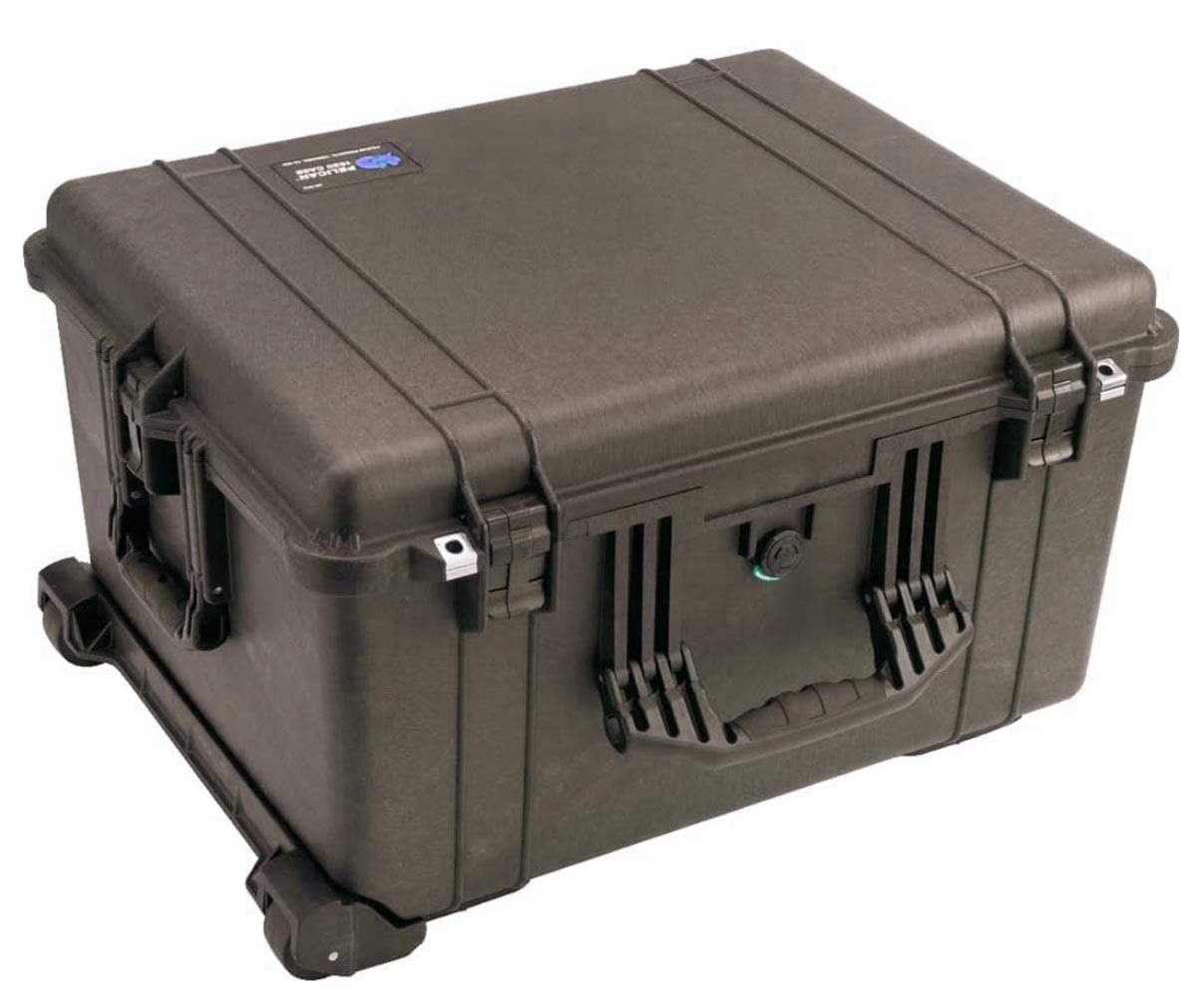
Figure 7. A Pelican model 1620 transport case. This was used for all my versions of liquid ventilation from LV2 onward. LV1 used a slightly smaller Pelican, but the 1620 turned out to be the minimum size to accommodate larger infusion and suction pumps.
7. The Pelican itself could do dual duty as an ice-and-water reservoir. Nested inside it would be the perfluorocarbon reservoir, which would require no bulky insulation, because the ice-and-water surrounding it would protect it from heat incursion. This valuable idea was contributed by my collaborator Gary Battiato.
8. While CCR had threaded a thin infusion tube and suction tube through the endotracheal tube, their small diameter restricted the flow rate. I chose to eliminate the thin tubes, and used the endotracheal tube for both infusion and suction cycles. This allowed some residual heat to affect the infusate, but the greater flow rate compensated.
9. Cooling with an ice-and-water mix. While CCR had already established this, it was worth emphasizing. Any infusate temperature below 0 degrees Celsius will risk freezing water in the lungs, but any temperature above 0 degrees will provide inadequate cooling. Ice absorbs a very significant amount of heat when it melts, and during the melting process, its temperature is stable, requiring no thermostat. It is really the ideal option for cooling perfluorocarbon liquid.
I obtained approval for these concepts from Steve Harris, the research director at CCR, and my first, very basic liquid ventilation setup (unimaginatively named LV1) is shown in figure 8. The perfluorocarbon reservoir is nested inside the Pelican case, with ample room for ice and water on the right-hand side. The pumps were a different color from the example in Figure 6, but their specifications were the same. The electronics of the cycle controller are shown in Figure 9. You can’t get much simpler than this.
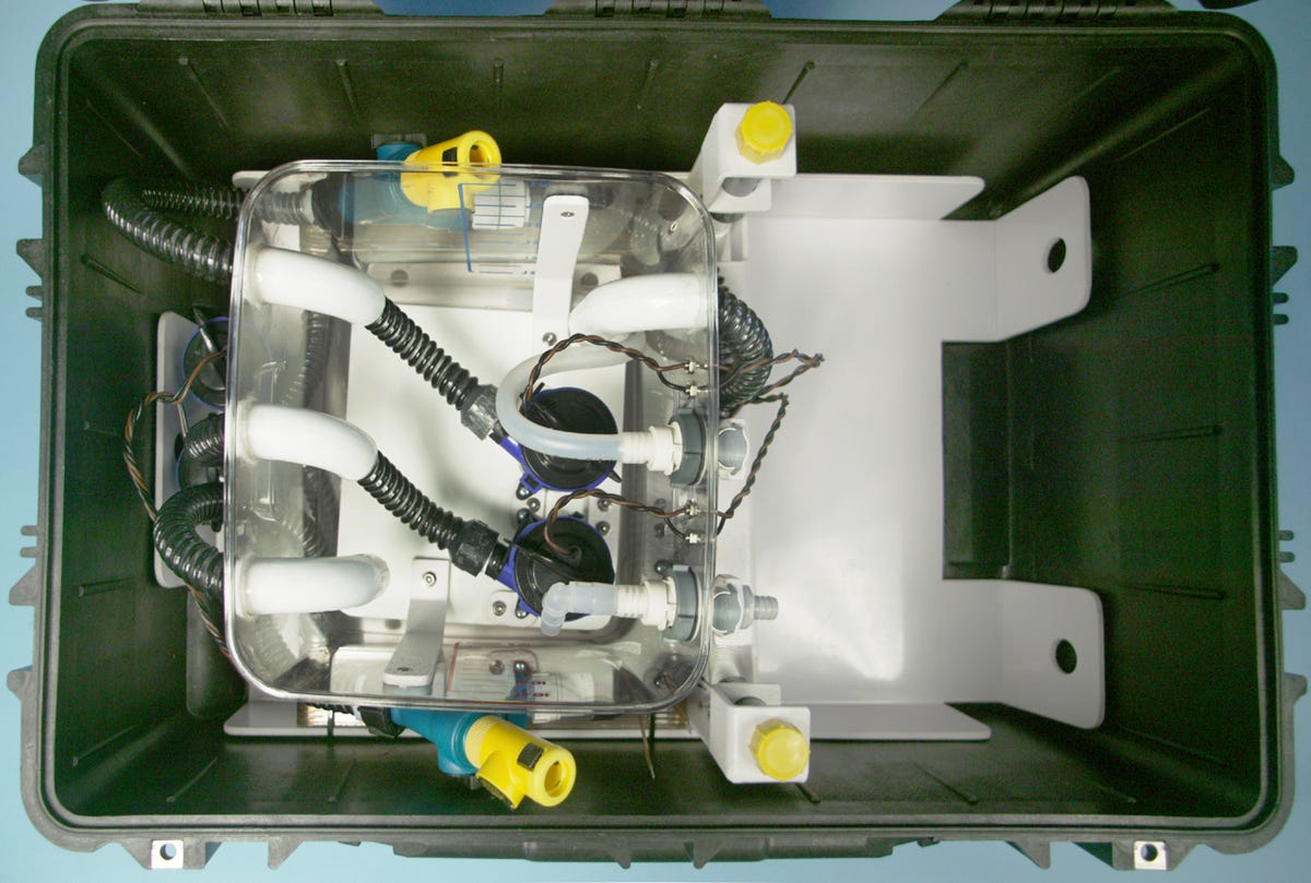
Figure 8. Viewed from above, LV1 was deliberately designed to be as basic as possible.
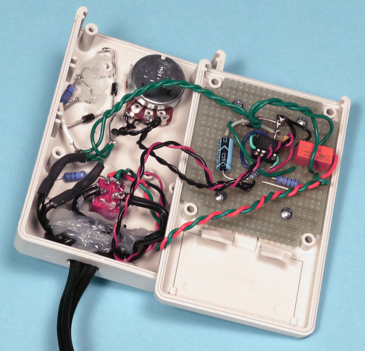
Figure 9. Elementary control electronics for LV1 consisted of a timer chip and a potentiometer.
To the surprise of everyone, especially me, the system worked well when it was tested in 2006. Rapid cooling was achieved, and the canine subject was up and around and wagging his tail the next day. This was a big relief to me, as I have mixed feelings about animal research.
What happened next was inevitable: When a designer builds something that works, the client asks for additional features. This led me to build LV2 in 2007. The perfluorocarbon reservoir with ancillary components was now mounted on a subframe for easy removal and cleaning, as shown in Figure 10. I also added battery packs inside a control panel, shown in Figure 11, capable of running the equipment for an hour. The control system was more sophisticated, although I still hadn’t resolved the issue of accurate flow-rate measurement. LV2 achieved cooling rates shown in Figure 12, initially approaching 1 degree Celsius per minute—more than 10 times the rate claimed in CCR’s patent.
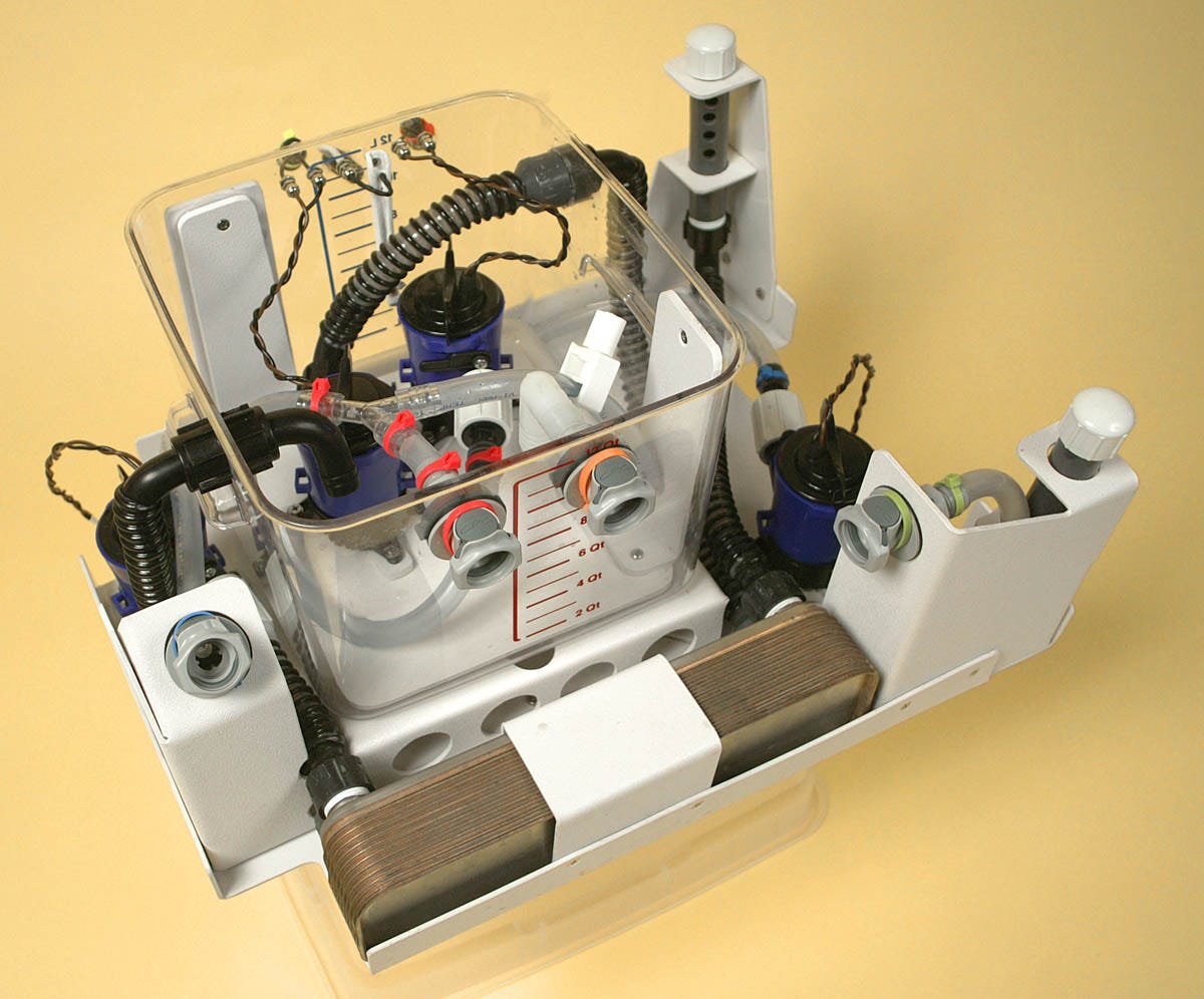
Figure 10. The perfluorocarbon reservoir from LV2.
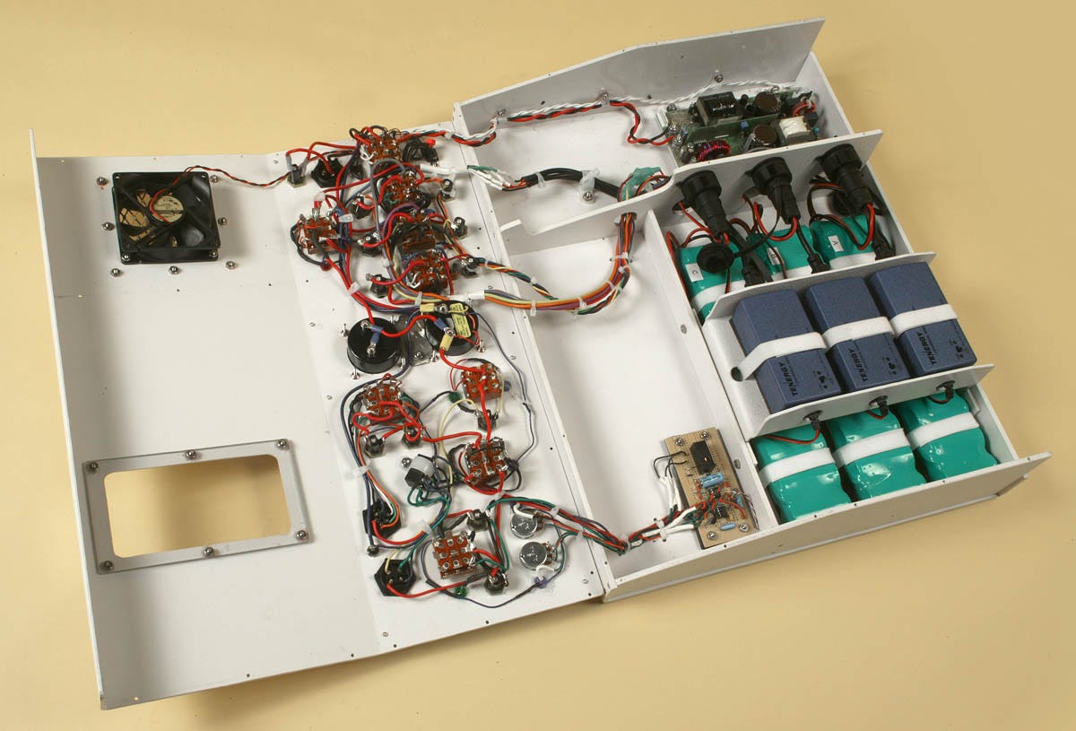
Figure 11. Inside the control panel for LV2. Much of the wiring was associated with the three green battery packs. Their output had to be balanced.
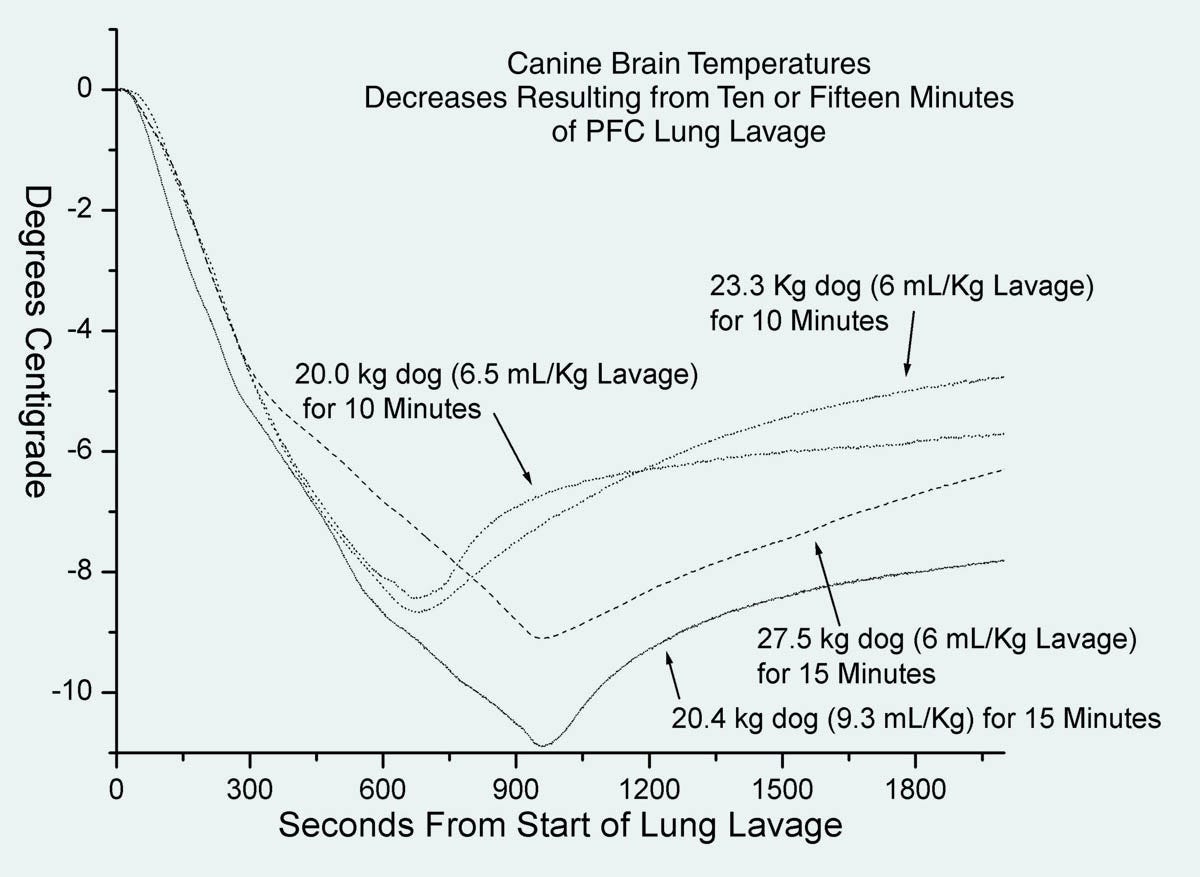
Figure 12. Cooling graphs show an initial reduction of almost 1 degree Celsius per minute. Cooling had to be curtailed around 9 degrees below normal body temperature, to prevent cardiac arrest.
Saul Kent now agreed that I should relocate in California, not far from Critical Care Research, to facilitate collaboration. I would work exclusively to develop LV3, which would include still more features. In addition, Saul wanted me to obtain a patent, which I wrote in collaboration with Steve Harris and an attorney. This required me to learn how to do drawings in the style dictated by the Patent Office, which required lines of a specific thickness, and no shades of gray. As for color—forget about it! The patent office style sheet had been designed in an era of fax machines, and had never been updated. Two of the many drawings are shown in figures 13 and 14.
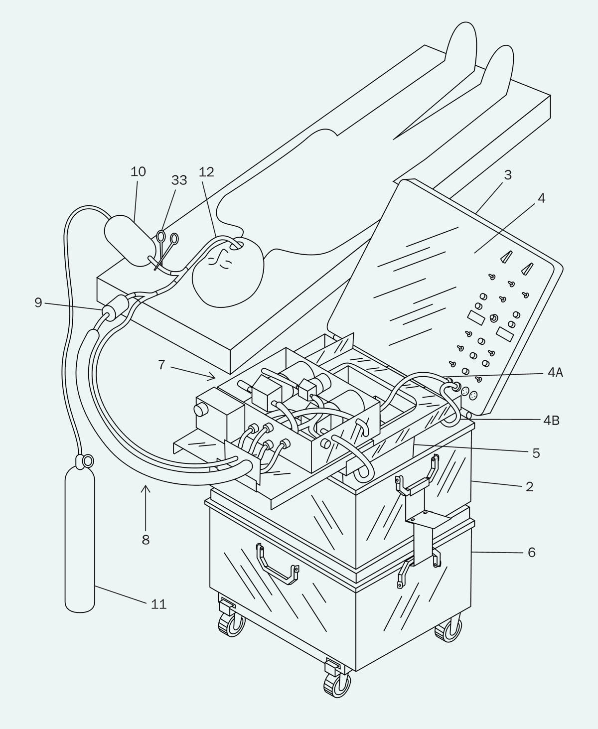
Figure 13. A patent drawing for LV3.
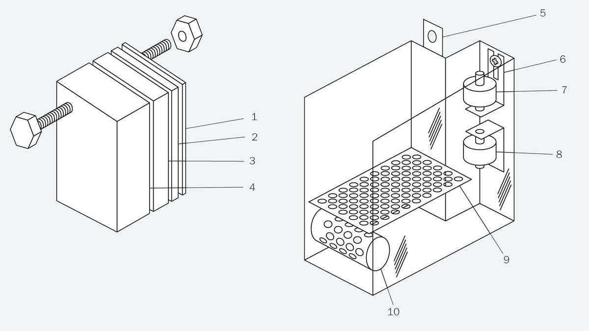
Figure 14. Patent drawing for the infusion measurement tank in LV3.
In LV3 I came up with a very basic system for flow measurement. I gave up trying to deal with flow meters that never worked properly. Each infusion volume was now pumped into a preliminary measurement tank, which had only two settings, “full” and “empty,” established by level sensors labeled 7 and 8 in Figure 14. Surging, sloshing, and turbulence were limited by perforated baffles. The contents of the measurement tank were then transferred into the lungs via a separate infusion pump.
The liquid volume of each infusion had to be set at the beginning of each experiment, using four “volume displacement tabs” (shown on the left in Figure 14). The operator selected a combination of tabs to be immersed in the tank, displacing some of the liquid. The thickness of the tabs increased geometrically, so you could displace any volume from 10ml (using only the thinnest tab) to 150ml (using all the tabs) in increments of 10ml. For those mathematically inclined, if the number of tabs was n, you would have 2^n –1 possible infusion settings.
Why not have an adjustable level sensor and use it to set the volume, instead of this rinky-dink tab system? Because level sensors were not happy with the residual surging and turbulence of the liquid. Also, many of them were expensive, and required control electronics with a suitable interface. I was still determined to keep things simple, and I supplied the operator with a list of tab combinations for each infusion volume. (Of course, this did require the operator to read the instructions.)
The speed of the infusion pump was controlled with that most basic electronic component, a rheostat. Thus, during setup, the operator could establish the infusion volume (supplied by Steve Harris using a simple formula derived from body weight), and the pump speed could be adjusted to deliver that volume within a specific time. From these numbers, it was easy to derive the actual flow rate—again, provided the operator of the equipment read the instructions.
I was now impatient to try the equipment in a cryonics case. It seemed to me that if someone had signed up for neuropreservation, the state of the lungs would not be a concern, since the body would be buried or cremated. What I wanted to know was whether my liquid-ventilation equipment would be compatible with chest compressions. You will recall that chest compressions are essential to circulate the blood cooled by liquid ventilation; otherwise, the procedure is pointless.
All of the tests so far had been conducted on living animals with beating hearts, and in any case, the canine rib cage is very different in shape from a human rib cage. The only way to test compatibility with a cryonics patient was to try it on a cryonics patient.
However, Saul was firmly opposed to testing it in cryonics, and seemed fixed on the idea of applying liquid ventilation in conventional medicine, where a short burst of rapid cooling can greatly reduce the risk of brain injury after cardiac arrest. In fact, if a liquid ventilation device could fit into an ambulance, it had the potential to save a lot of lives. I wrote about this in an article in Discover magazine, when LV3 was being tested.
As a compromise, I suggested to Saul that he should sell the intellectual property to a pharmaceutical company which would know how to guide a radical concept such as liquid breathing through the FDA certification process. We certainly didn’t know how to do that, and in fact we didn’t need to know, because we could include a “cryonics exemption clause” in any agreement, allowing us to use liquid ventilation in cryonics cases without paying any licensing fees. However, Saul didn’t want to sell or license the IP, which explains why my devices were never tested in cryonics for more than a decade.
The next step in the evolution of liquid ventilation was to automate it. Steve Harris was still squeezing a bag valve manually, to add gas to each infusion cycle. Infusion volume was being set manually. Pump speed was being set manually. I wanted a pushbutton system that would require minimal training and supervision. Text prompts should guide the operator through setup, should display numeric values, and also error messages. All of this could be achieved if I used a microcontroller, so in 2010 I taught myself how to program microcontrollers, and set to work. By this time I had relocated to Arizona, where I now had my own workshop, shown in Figure 15. This serene setting was greatly conducive to doing good work, but I ran into problems that I was unable to resolve.
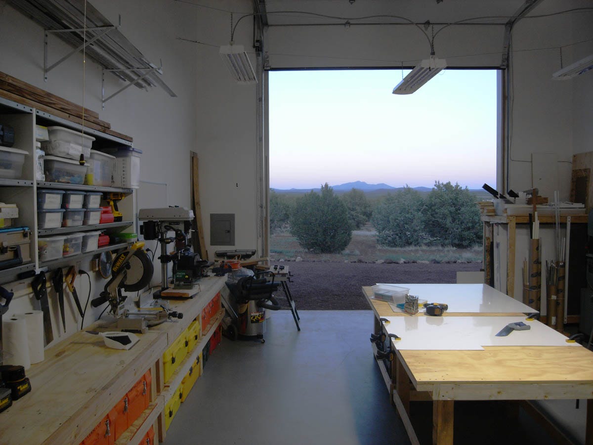
Figure 15. A workshop in the wilderness of Northern Arizona, where I struggled unsuccessfully to build LV4.
I became overwhelmed by the electronics. I ended up with eight microcontrollers sharing an I2C bus and my own system of interrupts for error handling. It was all hand-wired (as shown in Figure 16) and the long wire-runs started to plague me with capacitance effects. I lacked the necessary experience to make this work. “You should not be paying me to learn how to do this,” I told Saul.
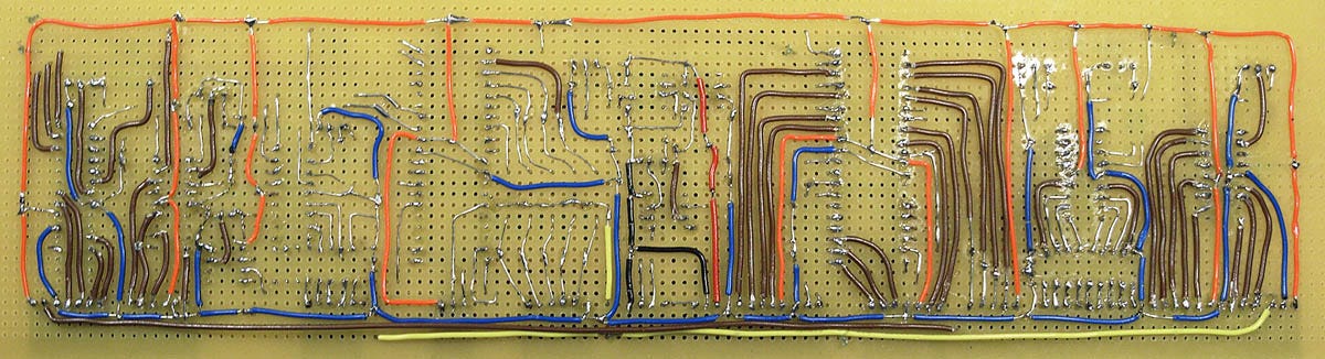
Figure 16. The main board for LV4 experienced capacitance effects and other problems.
A woman named Catherine Baldwin was now running Suspended Animation in Florida, and was commissioned to find an electronics engineer who would have the experience that I lacked. Catherine then took over the project, and that was the last I heard of LV4. If I had been in her position, I might have been asking Platt and Harris a lot of questions about prior art, but for whatever reason, she preferred not to.
Subsequently I was told that the electronics engineer whom she hired was unable to solve the problems that I had encountered, so he reworked the entire system using LabView software. This didn’t make sense to me, as LabView software required LabView hardware, which was heavy and used 110VAC. Still, I told myself that liquid ventilation was no longer my concern.
Time passed. CCR eventually said they were tired of waiting for a new version which they could use to continue their search for the ideal mix of perfluorocarbons, and they asked me to build a minimal update to LV3. Since LV4 had been surrendered to SA, I duly built LV5. This took about four months, and the finished result is shown in Figure 17. After that, once again, I forgot about liquid ventilation.
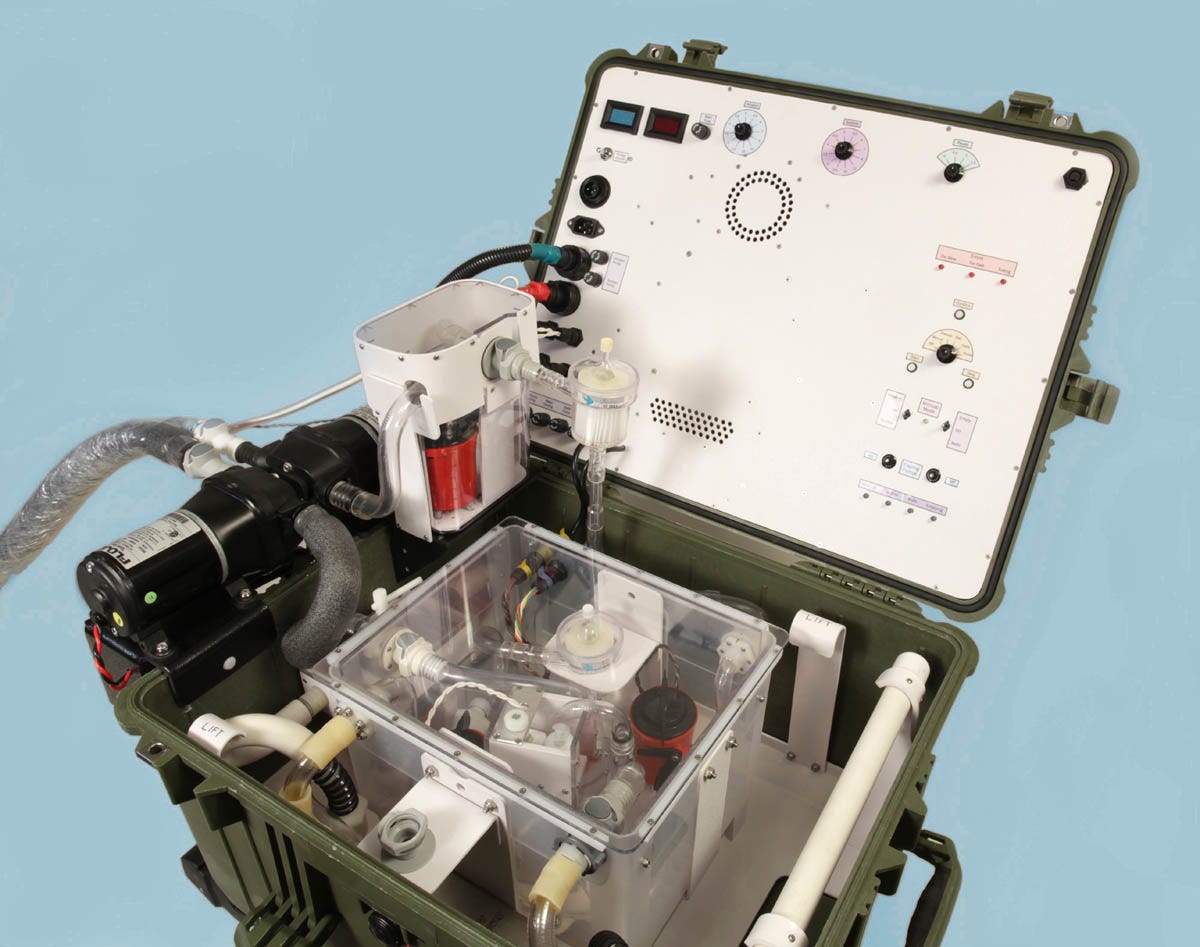
Figure 17. LV5 was a quick minor update for Critical Care Research.
Suspended Animation now moved to Florida and began their liquid-ventilation project all over again, starting from scratch, with new personnel who favored radically different concepts. Communication between Critical Care Research and Suspended Animation was very limited, and I was out of the loop anyway.
Finally I think it was veteran cryonicist Ben Best who requested a test that would compare LV5 with the new Suspended Animation system, because funding two competing systems seemed wasteful, and we should focus on whichever system worked better. Very kindly, Ben invited me to attend the “LV bake-off.”
I was fascinated to see the new SA system. Catherine Baldwin had run into a problem with a Pelican case, which had been damaged after being transported as checked airline baggage (probably the only time that this had happened in the history of cryonics standby deployment). Consequently SA were now using a Coleman ice chest, which I thought looked flimsy, but was internally reinforced with a metal frame. Figure 18 shows the equipment being lifted out of the ice chest, while Figure 19 shows it ready for use.
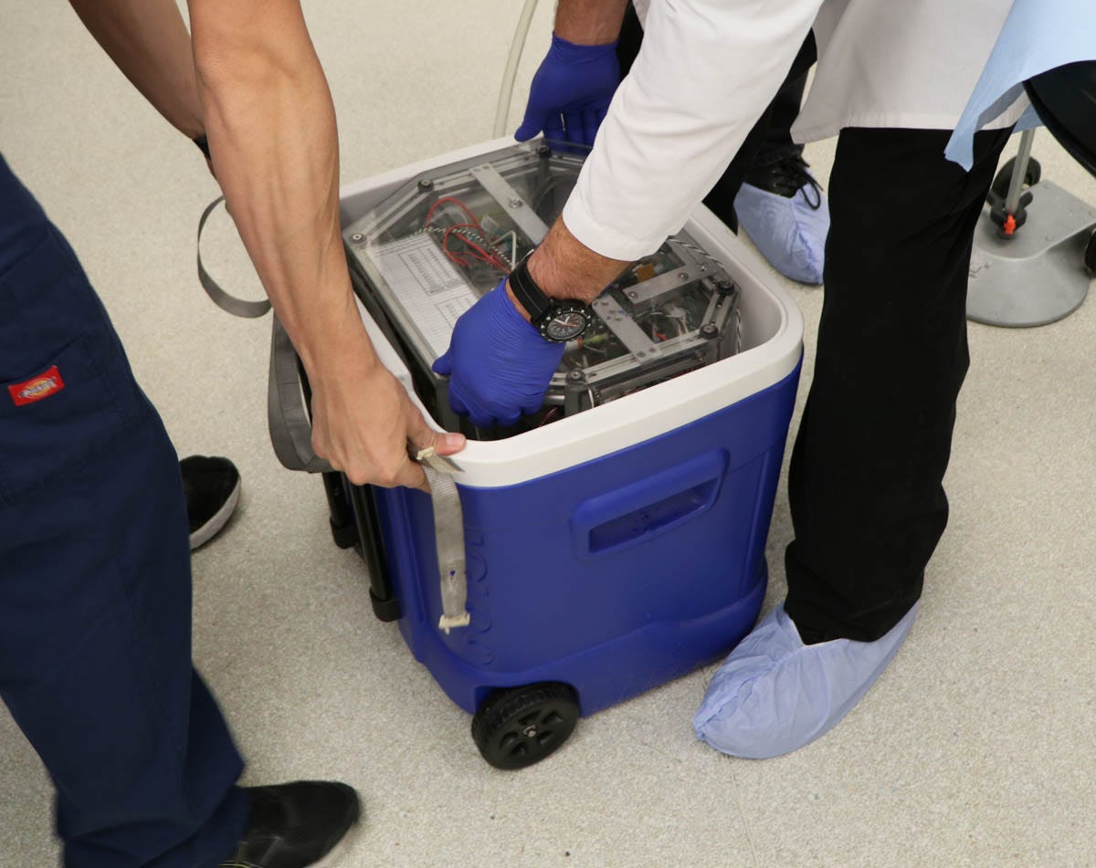
Figure 18. The second-generation liquid-ventilation device developed at Suspended Animation, being removed from the ice chest in which it was transported.
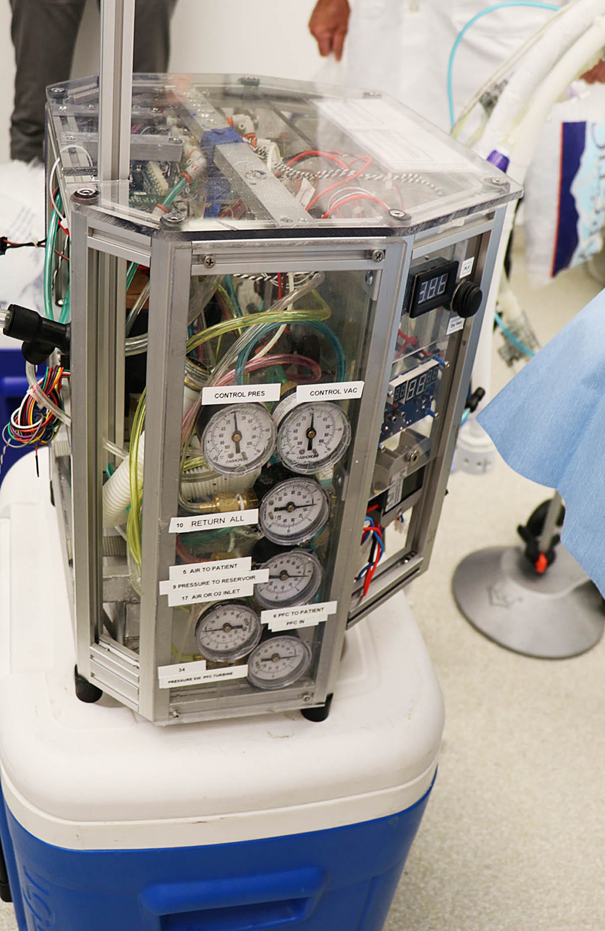
Figure 19. The device having been extracted from the ice chest.
I was impressed by the craftsmanship, which was impeccable. At the same time, I noticed that SA seemed philosophically opposed to my “keep it simple” design philosophy. It looked to me as if they would have a hard time fixing any fault, such as a tubing leak, inside the densely packed assembly. However, the people who had designed this thing were clearly professional engineers, while I was still afflicted with my amateur status. I wasn’t in a position to be critical.
SA had been granted patent number US10046126B2 which included many remarkably detailed graphics, three of which are reproduced here. Figure 20 provides another view of the equipment in Figure 19, and is notable for showing a large circular infusion reservoir that appears to be sealed. Figure 21 shows the infusion delivery tubing, which appears to be at least six feet long. The photograph in Figure 22 shows the actual tubing being deployed.
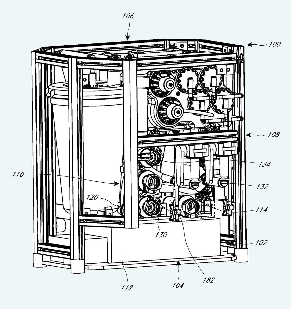
Figure 20. A drawing from the SA patent of equipment photographed in Figure 19.
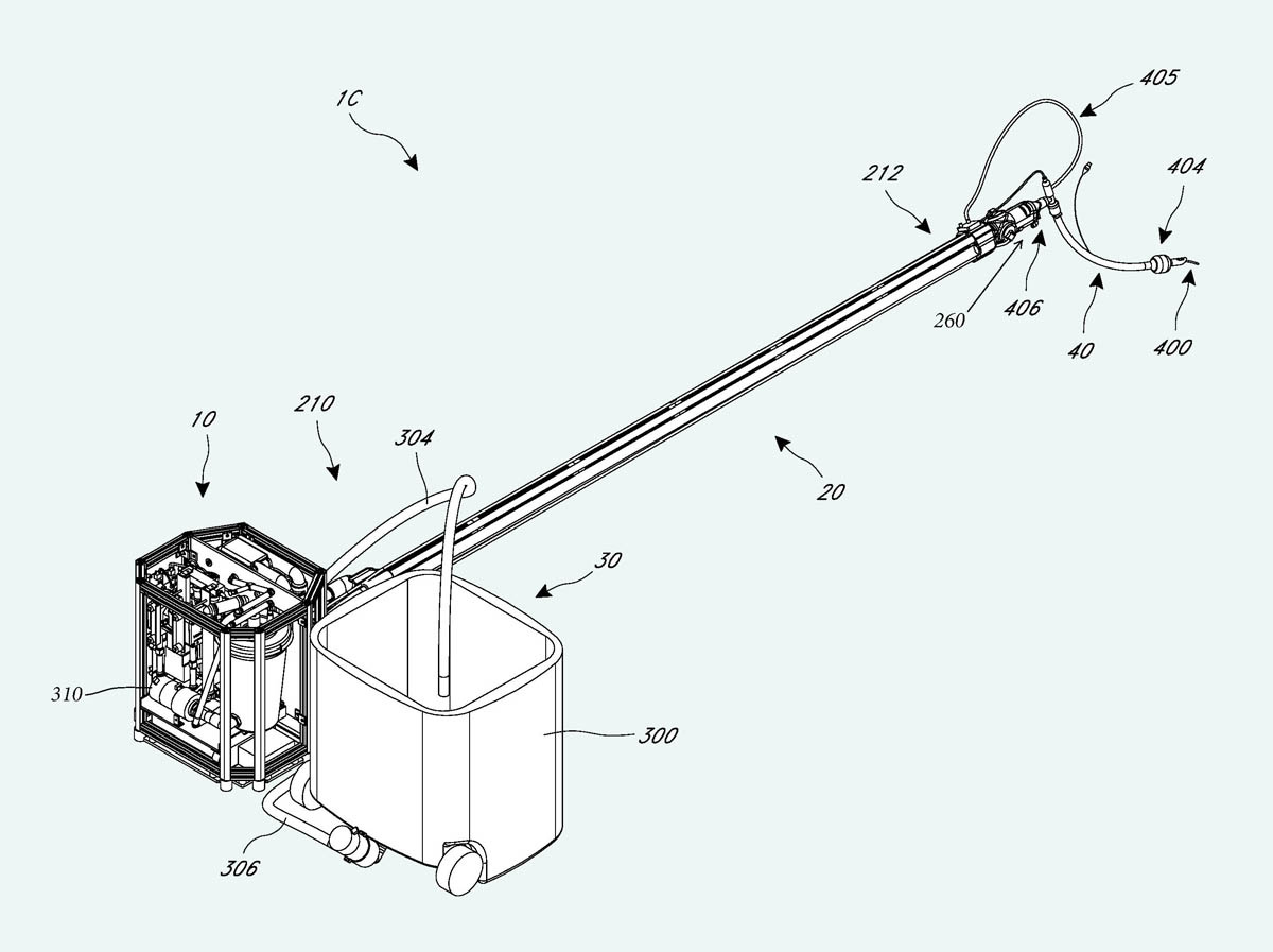
Figure 21. The long infusion delivery tubing illustrated in the SA patent.
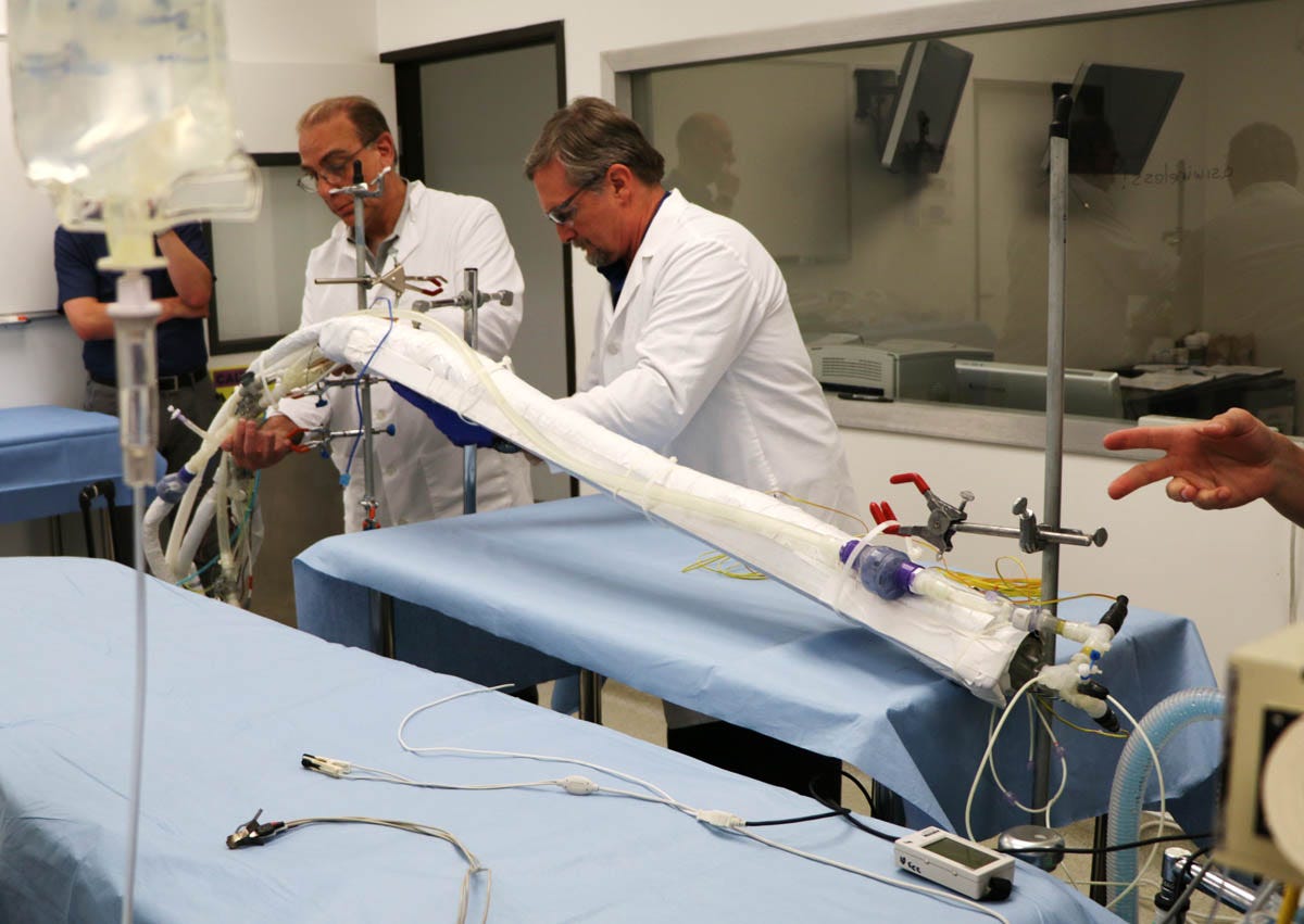
Figure 22. The infusion delivery tubing being deployed.
The rationale for the long delivery tubing is explained in the Summary section of the patent, which claims that in other liquid ventilation equipment (presumably mine), “the liquid may warm up again by the ambient air during its travel in the tube assembly before entering an endotracheal tube, leading to less efficient heat exchange.” They felt they could get better results if they chilled each infusion on its way to the patient, instead of pre-chilling it in a reservoir. This could also simplify the equipment by eliminating circulation pumps associated with the reservoir. The two design philosophies could be described as “in-reservoir cooling” and “in-tubing cooling.”
I had actually been concerned about the risk of heat getting into the delivery tubing when I was designing LV3. In that version, instead of merely using foam insulation, I added a jacket containing ice-cold water, which was circulated by yet another pump. However, the water in the jacket added to the weight of the infusion tube, making it unwieldy, and so far as we could tell, the extra cooling was negligible. Consequently, in my subsequent designs, I went back to using passive foam insulation.
The problem with the SA design was that because the perfluorocarbon entered the perfluorocarbon delivery tube near room temperature, the cooling system had to extract a lot of heat very quickly. This in turn required the tube to be rather long, but even that may have been insufficient, as during the demonstration I noticed they were adding salt to an ice-water mixture in a heat exchanger, to lower the coolant temperature below 0 Celsius.
The SA designers seemed to share my concern that chest compressions could conflict with liquid infusion cycles, possibly causing lung damage. To guard against this, they included a pressure sensor that would abort any infusion if the lung pressure rose above a threshold considered to be hazardous. My philosophy was rather different: Try the simplest possible system of timed infusions, to see what would happen. If liquid in the lungs caused problems, then I would try to figure out a way to deal with it.
Some time later, when LV5 was actually tested in conjunction with chest compressions in pigs (which have a rib cage closer to human configuration than dogs), a sensor showed that pressures inside the lungs never approached a level considered hazardous in conventional medicine. So, maybe there was nothing to worry about, although of course we won’t know for sure until equipment is tested on a human cryonics patient.
Lastly, Figure 23 shows the interactions between principal components in the SA system. I notice that the sealed liquid reservoir is connected with a vacuum pump, and the reservoir is fitted with a valve to connect it with the lungs. This same arrangement was shown in the CCR patent, but Steve Harris once told me he had abandoned the idea. I never asked him why, because it was much easier for me just to use a suction pump that would stop and start as required. Dr. Harris is no longer alive, so we may never know why he disliked a vacuum pump and a sealed reservoir.
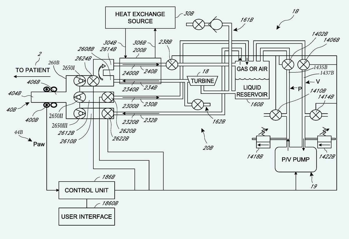
Figure 23. A diagram from the SA patent.
Overall, I saw the SA system as a minor masterpiece of equipment design, if you began with the preconception that it should include the kind of precautions necessary in medicine. In medicine, the primary rule is to “do no harm”; but cryonics is a bit different. If a cryonics patient specifies that only his head or brain should be cryopreserved, he may not care if some minor harm occurs to his lungs in the course of accelerating his cooling rate.
Unfortunately, during the comparison test against LV5, an error was made in the operation of the SA equipment, producing fatal results. This error resulted in the SA project being cancelled permanently. I regret that I never had an opportunity to inspect the equipment more thoroughly, as I’m sure I could have learned more lessons from it.
Since CCR had possession of LV5 and was reluctant to surrender it, Alcor was asked to collaborate with me in building a version specifically to apply liquid ventilation to cryonics cases. However, I learned that Alcor had a Scientific Advisory Board, and Brian Wowk, an important member of that board, was very insistent that money would only be allocated for me if the Alcor version was as similar as possible to LV5. Brian’s reasoning was simple and persuasive: If we were tempted to innovate, each new idea was liable to create its own new set of unintentional consequences. LV5 had been proven in many trials, so why not stick with something that had been shown to work? I totally agreed with this outlook.
I contracted with Alcor to build the hardware for their version, subject to Brian’s condition. The device would be designated LV6. Alcor’s employee Steve Graber would write the software for microcontroller(s) to run the device, since I thought he was a lot more experienced in that area than I was.
However, Steve is a very creative person, and started coming up with a lot of interesting new ideas for the hardware, such as using an injector similar to an automotive fuel injector, to add infusate to the stream of gas during infusion cycles. He then developed some 3D renderings, and stated that his goal was to reduce the size of the equipment radically, so that it would fit into a backpack.
As a salaried employee, Steve was under the authority of his CEO, who seemed disinclined to limit his creativity. By comparison, as a consultant, I was bound by the agreement that I had signed. Since the project was now going to include some radical innovations, I could not pursue it.
Steve did show me some 3D renderings, and during a visit I saw the beginnings of his device. It was difficult to photograph, but I took the picture shown in Figure 24. All you can really tell from this picture is that the same Johnson pumps that I used in all my versions are visible (apparently mounted on their sides), and there is a heat exchanger.
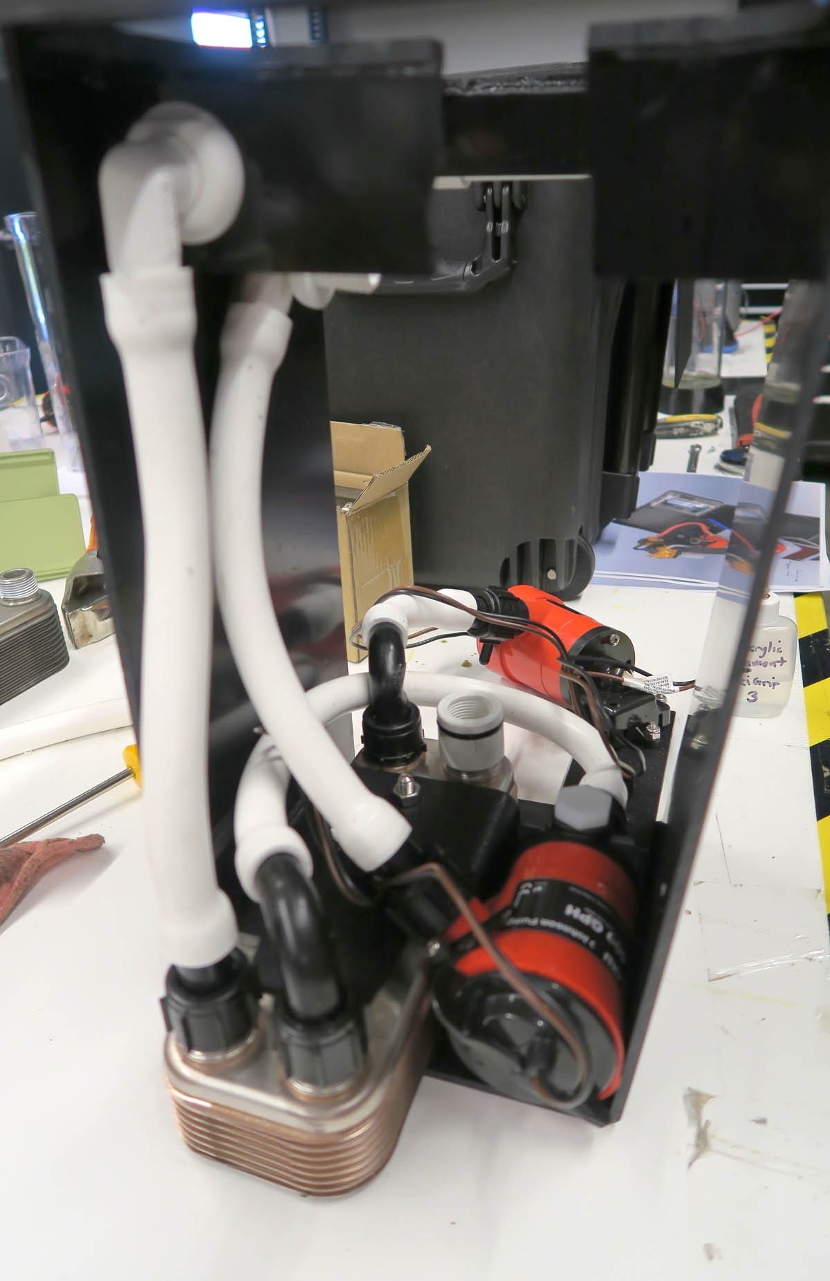
Figure 24. My rather inadequate photograph of Steve Graber’s initial design at Alcor.
After this, Steve followed his own path. I don’t know how far he got with this version, but I did see a video in which he demonstrated a completely different setup in his workshop, mounted on a vertical panel. If he had developed a version suitable for deployment in a cryonics case, I would expect to have seen a picture of it by now. If I’m wrong about this, I invite a correction from Alcor.
My lengthy saga describing attempts to do something that wasn’t rocket science now reaches the present time.
In 2023 Biostasis Technologies asked me to develop a version of LV5 that they could use in cryonics cases. Critical Care Research had been shut down, but LV5 was in storage at the home of the person who had operated it, so I went to California to retrieve it, hoping that some of it, at least, could be salvaged.
Unfortunately, its custodian was unaware that it had been stored half-full of water. Many components were corroded, and I found black deposits that appeared to be mold. I decided that a totally new copy had to be built, and it wouild be designated LV5A, as I was still mindful of Brian Wowk’s admonition to avoid unnecessary innovation. I completed and delivered LV5A to Biostasis in 2024.
The issue of liquid volume measurement has now been settled by getting rid of the volume displacement tabs and using a new level sensor from Madison, Inc, a company which specializes in this equipment. While most of their sensors are scaled for large vessels such as 55-gallon tanks, they recently marketed smaller ones that would barely fit within size constraints dictated by the Pelican case which I still favored as the ice-and-water reservoir.
The sensor consists of a vertical stainless-steel tube containing a ladder of fifteen 150-ohm resistors in series, with taps connected to reed switches. A doughbut-shaped float containing a small neodymium magnet slides up and down the tube, activating each reed switch in turn. This is identical in principle to the sensors now installed in the fuel tanks of many cars and motorcycles. The precision of the sensor is limited by the number of resistors, and the output of the sensor that I chose for LV5A consists of a resistance that varies from 150 to 1,500 ohms in 10 steps. I decided that 10 was acceptable, although I shaped the measurement tank like an hour glass, so that the electrical resistance of the output would be more sensitive to liquid level variations at the center of the volume range than at either extreme.
I also added a return volume measurement tank, so that the operator could determine if suction cycles were yielding a volume approximately equal to infusion cycles. This would provide a warning if liquid was accumulating in the lungs, which had sometimes been a problem at CCR.
Lastly, I shifted operator control from the main panel in the lid of the Pelican case, to a box that allowed selection of infusion or suction from a location near the patient.
Currently the equipment is waiting for a minor upgrade to simplify its setup and its volume, time, and pump speed displays. At that point, finally, I hope it may be tested in a cryonics case. I remain optimistic that chest compressions are compatible with liquid ventilation cycles in a human cryonics patient, because gas is so much more compressible than a liquid, and the addition of at least 500ml of air or oxygen to each infusion cycle will probably allow the lungs to withstand chest compressions without damage. Of course, my outlook is speculative.
Some photographs of LV5A are shown in figures 25 through 28.
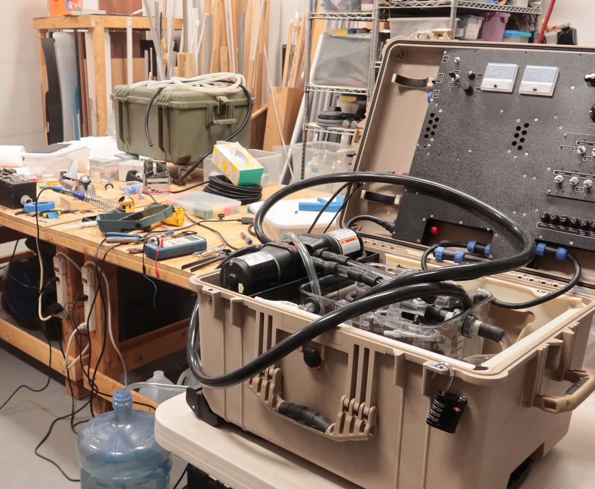
Figure 25. LV5A being tested in my workshop.
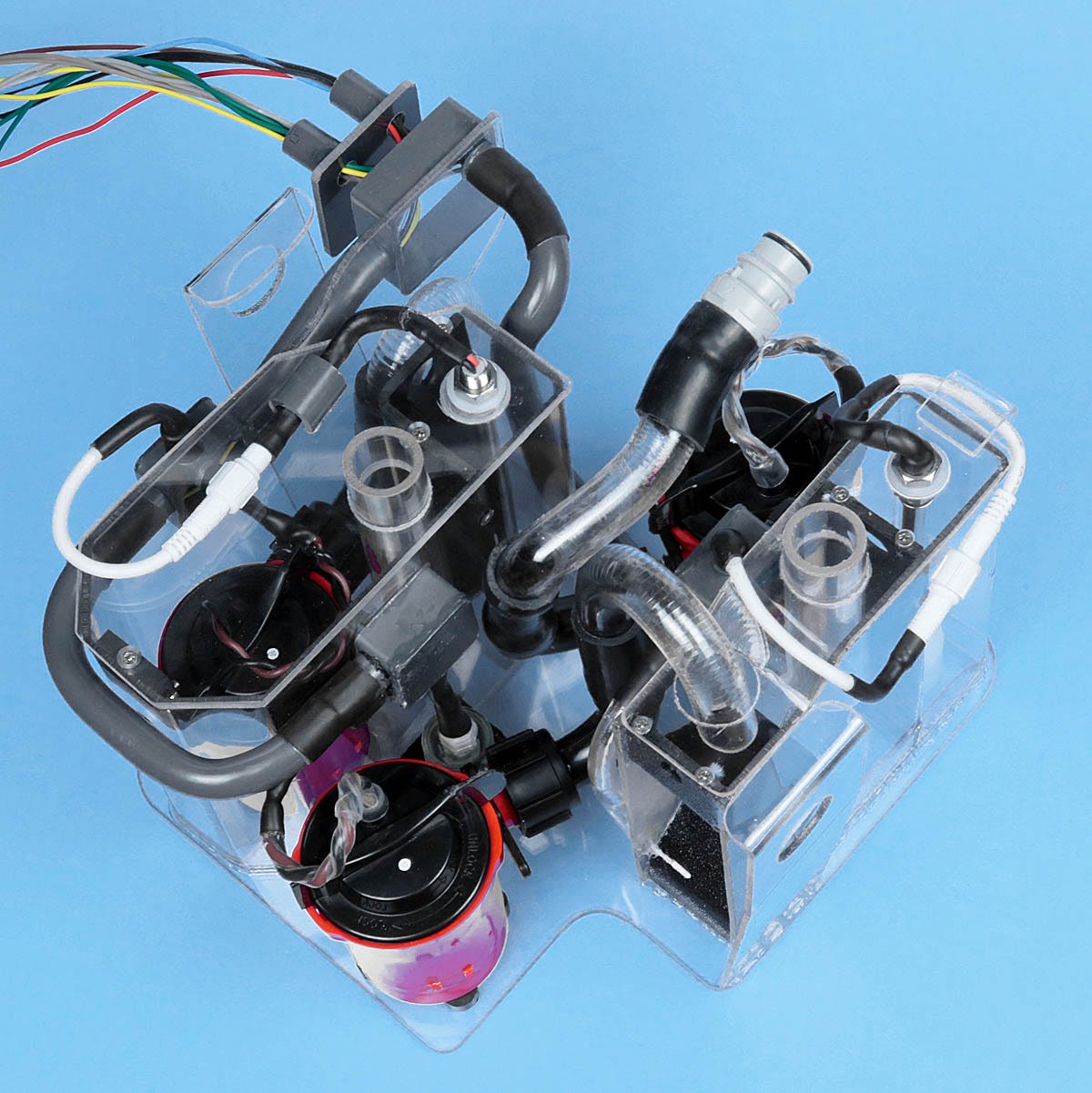
Figure 26. The return measurement tank (left) and infusion measurement tank (right), which normally sit inside the main perfluorocarbon reservoir in LV5A. Gray tubes are waterproof electrical conduits containing wiring for pumps and sensors.
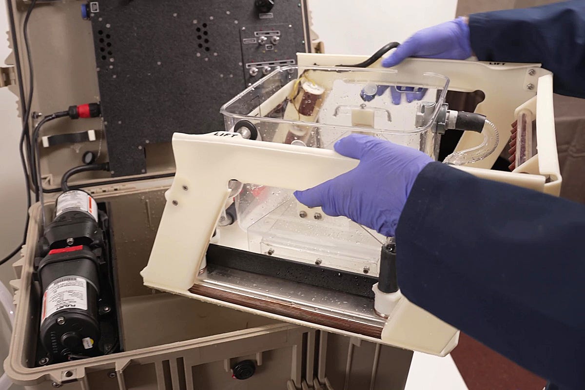
Figure 27. Infusion and suction pumps are at left. These are diaphragm pumps, which can deal with a mix of liquid and gas. The entire frame of LV5A lifts out for cleaning.
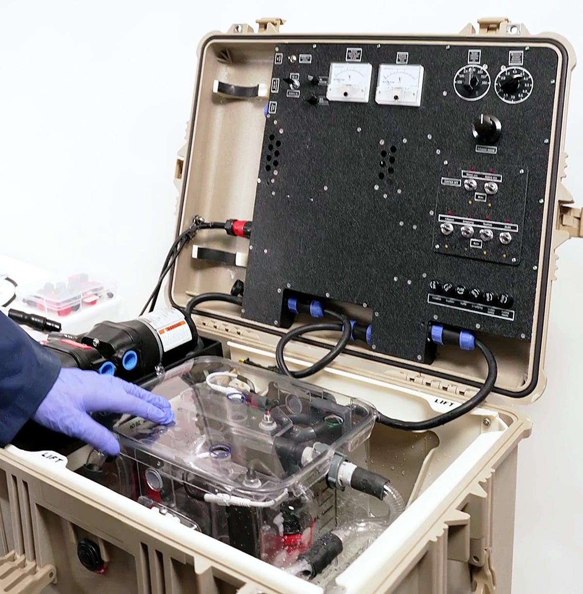
Figure 28. The analog meters will be replaced by digital displays, but in other respects LV5A is ready for a cryonics case.
This adventure began more than 25 years ago, and should have reached an outcome long before now. Conflicting design philosophies, an irresistible temptation to innovate, my own lack of technical knowledge in some areas (especially control electronics), design complications, interruptions in financing, and intercompany rivalry have all played a part in delaying liquid ventilation.
One question remains, regarding the news item that I mentioned at the beginning of this text. What is Alcor’s new patent all about? What does it portend, and how does the system that it describes differ from others that preceded it?
The patent number is US12257385B2, and is easily inspected online. The application was filed in September, 2021, slightly more than two years after I saw Steve Graber’s work in progress during 2019. The patent is very brief, including only four diagrams, the second appearing almost identical to the first. I have reproduced this diagram in Figure 29, below. The third diagram in the patent merely shows an endotracheal tube with three separate extensions, while the fourth is a very simple flow chart showing the two principal cycles of infusion and suction.
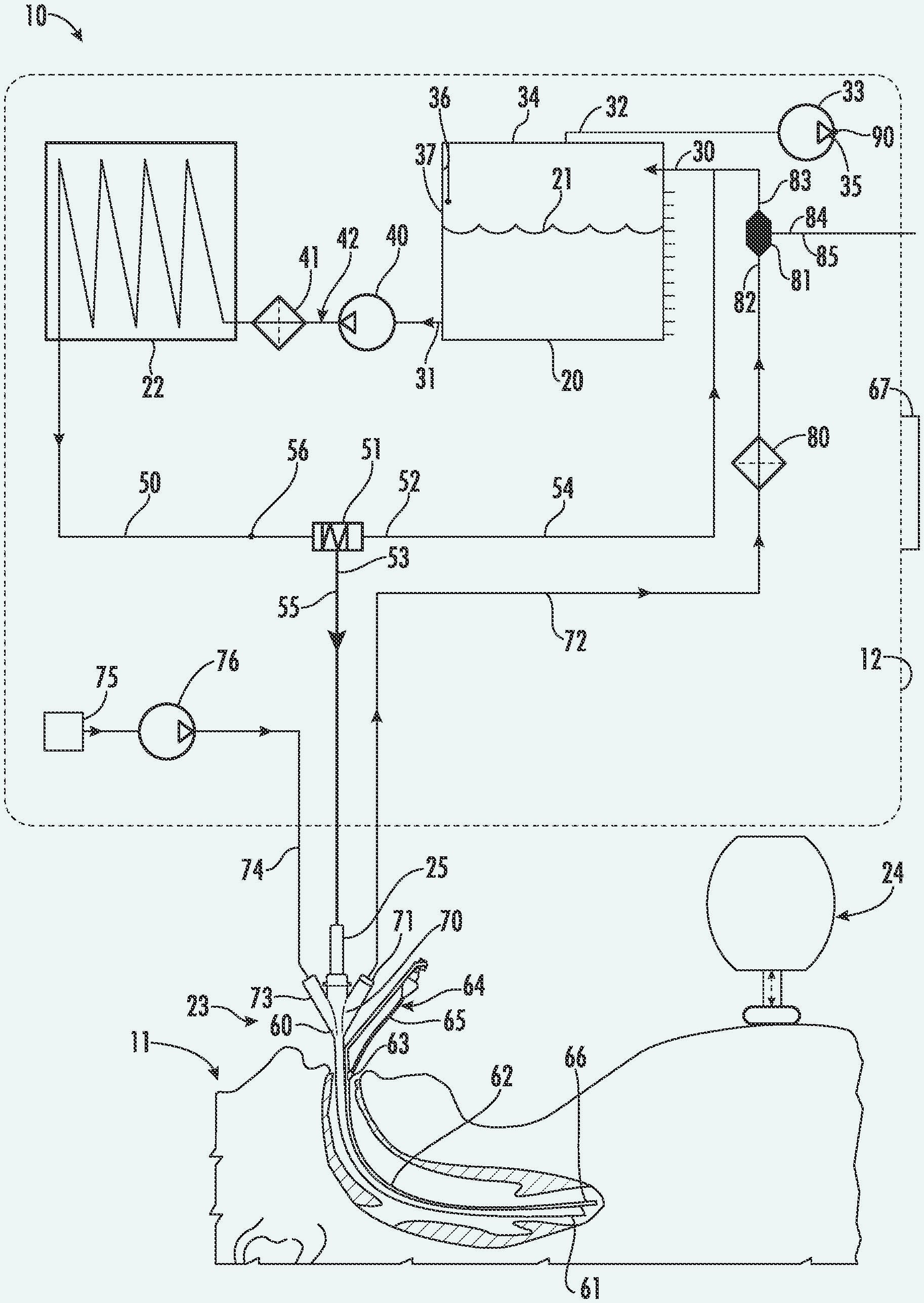
Figure 29. The principal diagram from the Alcor patent issued in April, 2025.
The claims of the patent itemize a perfluorocarbon reservoir, a pressure sensor, and a heat exchanger, all of which have been essential components in previous liquid-ventilation devices. A sealed reservoir is specified with a suction pump; this concept was used previously by SA, and also by Critical Care Research before they abandoned it.
A fluid injector is shown, controlled by the pressure sensor, which seems similar to the SA concept. A three-position “extractor valve” is included, but its method of operation is unclear.
Text in the patent reads:
. . .the housing 12 is a hard- or soft-shelled backpack, such that the system 10 can be carried into terrain for remote operation of the system 10. In a backpack embodiment of the housing 12, the constituent structural elements and features of the system 10 are packed tightly together to conserve space. For these reasons, FIG. 1 shows the housing 12 without a specific shape and without a specific arrangement of elements and features. . . .The round-cornered rectangle displayed as a dotted line in the diagram is labeled 12, and is identified as the backpack. Even allowing for the components to be “packed tightly,” I am puzzled that it can contain component number 22, which is identified as a “chiller.” Any type of refrigeration unit would require a power supply, and since none is shown in the diagram, perhaps it has to be plugged in to an electric outlet. Similarly, I am doubtful that item 75, identified as “oxygen supply,” can fit inside the backpack. Perhaps an external tank is necessary, although it is not shown.
The description in the Alcor patent includes some statements which I find odd. For example, “the performance of chest compressions on lungs filled with PFCs can be traumatic,” and, “a fully-infused bolus of PFC in the lungs during a compression will over-pressurize and damage the lungs and can kill the patient.” These statements of fact seem to suggest that chest compressions have been attempted on human patients in conjunction with total (gas-free) liquid ventilation. But I have not seen any report that chest compressions have ever been attempted in conjunction with any form of liquid ventilation on a human patient, and total liquid ventilation was abandoned at CCR many years before this patent application was filed.
Since the patent does not include a drawing of any actual apparatus, I wonder if a completed device existed as of September, 2021. Alcor’s news report of 2025 did not contain a picture.
In an effort to get more information, I emailed Alcor and asked these questions:
Has any liquid ventilation device been completed by Alcor?
Is any work still proceeding to develop liquid ventilation at Alcor?
Is the recent patent an accurate guide to current plans for liquid ventilation at Alcor?
Does Alcor intend to use liquid ventilation in cryonics cases?
Does Alcor have any comment on this statement:
"If an organization presents a report in an optimistic style, containing information that appears to be misleading or incomplete, I am concerned that trust in cryonics may be weakened, and all organizations may be affected."
I received a reply from Amya Anderson, which simply stated:
“Alcor does not have any response or comment to your inquiries. Thank you.”
Apparently she was writing on behalf of the organization, even though a list of employees at https://www.alcor.org/library/alcor-staff/ does not include an Amya Anderson.
So now you know as much as I know.
Opinions expressed in this text are those of the author, and do not necessarily represent the opinions or beliefs of Biostasis Technologies.
All photographs in this article are copyright by the author.
US6694977B1 - Mixed-mode liquid ventilation gas and heat exchange.
US8465535B2 - Portable apparatus and method for the administration of heat exchange in the lungs of a mammal.
US5706830A - Liquid ventilator system and use thereof.
US20100319691A1 - Vacuum and positive pressure ventilation systems and methods for intrathoracic pressure regulation.
US6149624A - Apparatus and method for the rapid induction of hypothermic brain preservation.
US20160271348A1 - Indirect measurement in a total liquid ventilation system.
US20210106746A1 - System and method for cardiorespiratory support.
US20210077759A1 - Liquid ventilator and method to induce tidal liquid ventilation and/or hyporthermia.
US10046126B2 - Apparatus and method for delivering fluids and/or gases to the lungs.
US12257385B2 - Liquid ventilation system.
1. “Spring Growth – The Alcor Newsletter.” Alcor Foundation: https://www.alcor.org/2025/04/spring-growth-the-alcor-newsletter/ accessed April 30, 2025.
2. “The number of alveoli in the human lung,” by Matthias Ochs and multiple coauthors. National Library of Medicine: https://pubmed.ncbi.nlm.nih.gov/14512270/ accessed April 30, 2025.
3. “Tennis Courts in the Human Body: A Review of the Misleading Metaphor in Medical Literature,” by Amogh Ananda Rao and Smilee Johncy. Natural Library of Medicine: https://pmc.ncbi.nlm.nih.gov/articles/PMC8863270/ accessed April 30, 2025.
4. The Engineering Toolbox. https://www.engineeringtoolbox.com/thermal-conductivity-d_429.html accessed April 30, 2025.
5. “Survival of mammals breathing organic liquids equilibrated with oxygen at atmospheric pressure” by L. C. Clark, Jr and F Gollan. Science 24, June 1966: Vol. 152 no. 3730. https://pubmed.ncbi.nlm.nih.gov/5938414/ accessed April 30, 2025.
6. “The Feasibility of Liquid Breathing in Man” by Johannes A. Kylstra, MD. Sponsored by Duke University Medical Center, Durham, NC 27710 for the Office of Naval Research. https://apps.dtic.mil/sti/tr/pdf/ADA037089.pdf accessed April 30, 2025.
7. “Liquid Ventilation” by Thomas H. Shaffer PhD, Marla R. Wolfson PhD, Leland C. Clark Jr. PhD, DSc. Pediatric Pulmonology 14:102-109 (1992). Wiley Online Library: https://onlinelibrary.wiley.com/doi/10.1002/ppul.1950140208 accessed April 30, 2025.