.png)

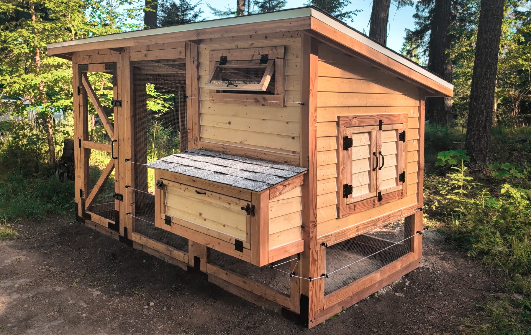
This summer, I built a relatively big, walk-in chicken coop. We live in a place with grizzlies, mountain lions, and fairly harsh winters, so the structure is a bit overengineered. It has double walls, double-pane windows (built by my wife), four electric outlets, and an electric fence that surrounds the outer “run”, which would be otherwise protected only by some 19 gauge steel mesh:
The feature we regretted not incorporating from the get go was an automatic inner door for the fully-enclosed box where the chickens nest and sleep at night. This would have allowed us to leave for a couple of days without needing anyone to stop by to let the chickens in an out.
There are some ready-made solutions for this, but they all require tearing out the existing hinged door and replacing it with a garage-door-style mechanism. Well, UNTIL NOW!
Here’s the device in action, with some added cat- and chicken-related comedy:
In the video, I’m covering the front-facing light sensor for about a minute to simulate dusk and trigger the closing of the door.
What I liked about the project is not that it was challenging. It was quite the opposite: modern technology made it much easier and faster than what would have been possible 2-3 decades ago.
I started with a relatively cheap but well-sealed and all-metal worm gear motor (Amazon product link). The motor needs 12 V, idles at 30 RPM, and delivers about 35 kg·cm of stall torque. The output shaft is coupled to an 8 mm universal joint to make a 90° turn. This angle locks the joint; it was just the easiest way to couple the motor to an 8 mm stainless steel rod without any welding or machining. The other end of the rod goes through a stainless rod-end bearing that’s screwed directly into the door frame. The total cost for the merchandise was around $35.
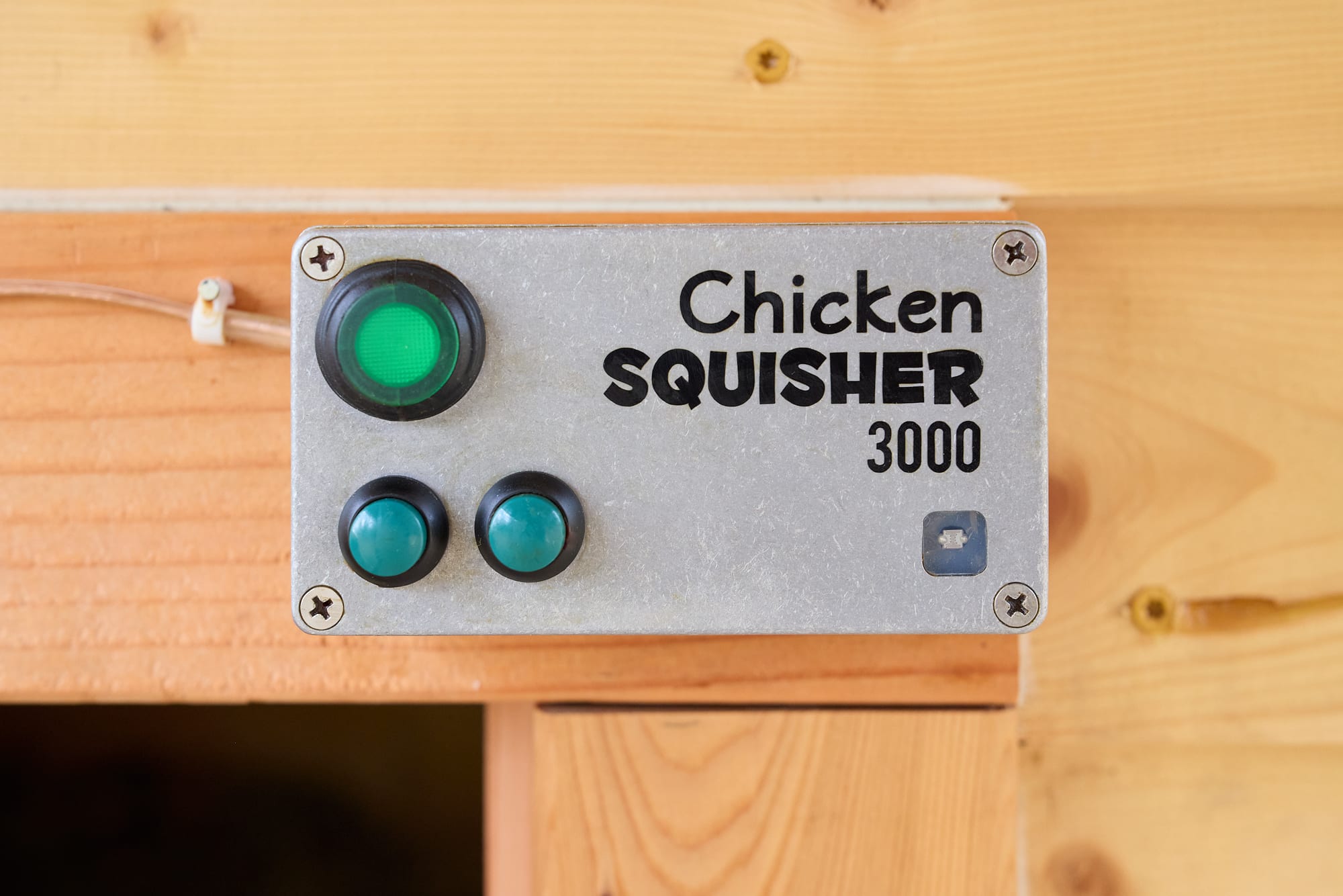
On the control side, the electronics are housed in a cast aluminum project box with a sticker made on a vinyl cutter and with several holes drilled for for “emergency” manual operation buttons (TE PB6B2HS6M3CAL00), along with a a waterproof power switch (CW industries CW246-ND). I also added a fitted acrylic window for a cadmium selenide photoresistor secured with a glob of translucent silicone.
The control circuit is exceedingly simple:
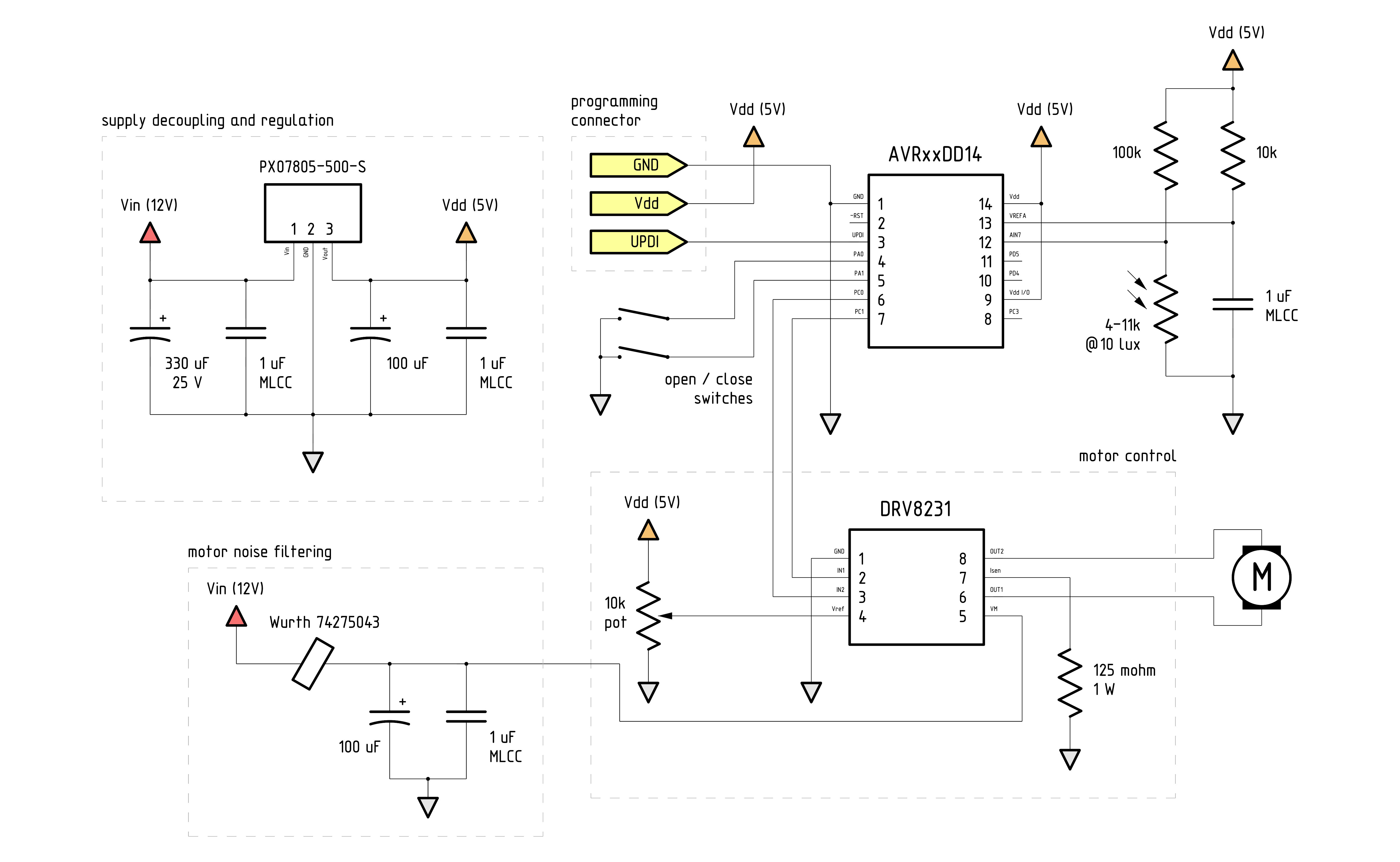
Power for the device is provided by a 12 V, 3 A Meanwell APV-35-12 PSU ($7.50). This is housed in a separate electrical box, wired directly into the mains. The PSU outputs 12 V DC, which is then converted once more to 5 V for the ICs. For this task, I used a PXO7805-500-S switcher simply because I happened to have one in the drawer; that said, almost any linear or switching regulator should do.
The main light-sensing element is Advanced Photonix NSL-A6009, a fairly standard cadmium selenide (CdS) photoresistor with a resistance of about 4-11 kΩ at 10 lux; in practice, it reads around 400 kΩ at the edge of twilight, and around 10 kΩ right around sunset. This element is connected to the ADC input of a Microchip AVR Dx series 8-bit microcontroller. A sub-$1 unit, such as AVR16DD14, should be more than enough.
Back in the day, a circuit like this would be implemented without programmable logic. That wouldn’t save us any money or time; further, we’d inevitably lose some flexibility with the operating plan. In my design, I rely on MCU pulse-width modulation to operate the motor at roughly 25% the speed and torque for the bulk of the movement; this avoids startling or pinching the chickens, but still lets me ramp it up to 100% for the final seal (when closing) or the initial pull (when opening). This should hopefully make the device more reliable in the presence of dirt, snow, or ice.
The microcontroller is interfaced to a Texas Instruments DRV8231 motor driver; this is yet another $1 part that takes place of a more complicated, multi-component H-bridge control circuit of the old. The chip uses current sensing and internal PWM to further limit stall current. The potentiometer that sets the current can be adjusted for the desired limit to avoid crushing the chickens even if all other safeties fail.
The logic implemented with the MCU is even simpler than the circuitry. Source code can be found here; in a nutshell, it configures the ADC for 10-bit single-ended operation and then accumulates 10 measurements over the course of one minute to decide if it’s day or night. At dawn, the voltage at the midpoint of the resistor ladder formed by the LDR and a series 100 kΩ resistor is:
\(\frac{10k\Omega}{(10k\Omega + 100k\Omega)} \cdot 5 \textrm{V} \approx 0.45 \textrm{V}\)
…which corresponds to an ADC reading around 90/1024. If the illumination level is higher than that, the system assumes it’s daytime and opens the door.
After dusk, the voltage is:
\(\frac{400k\Omega}{(400k\Omega + 100k\Omega)} \cdot 5 \textrm{V} = 4 \textrm{V}\)
This corresponds to an ADC reading in the vicinity of 800/1024. If the reading is higher than that, the system assumes night and shuts the coop door. The hysteresis afforded by the wide spacing of the “open” and “close” conditions prevents erratic behavior if the illumination level fluctuates a bit.